Page 1065 of 1216
BODY - Troubleshooting23-21
1 2. Warning Light, Key Reminder Switch, Buzzer Circuit 1IIJUNCTION
BLOCK
WARNING LIGHT
gCTy4;NATION
c-7,,7L,,l7,/\
00IOA
IOA
2:y47
.---
141I
I
I
I
I
I
1I
3
2
11
I
I
I13
-I_---
10IGNITION SWITCH
SUB FUSIBLE LINK @AUTOMATIC
SEAT BELT
CONTROL UNIT
t
11 WG
KEY REMINDER
6
\IL!>
Nhen ke
8emoved
13
+ installed
J
2
1SEAT BELT
WARNING BUZZER
20
w
IIem
Page 1067 of 1216

BODY - Troubleshootinn23-23
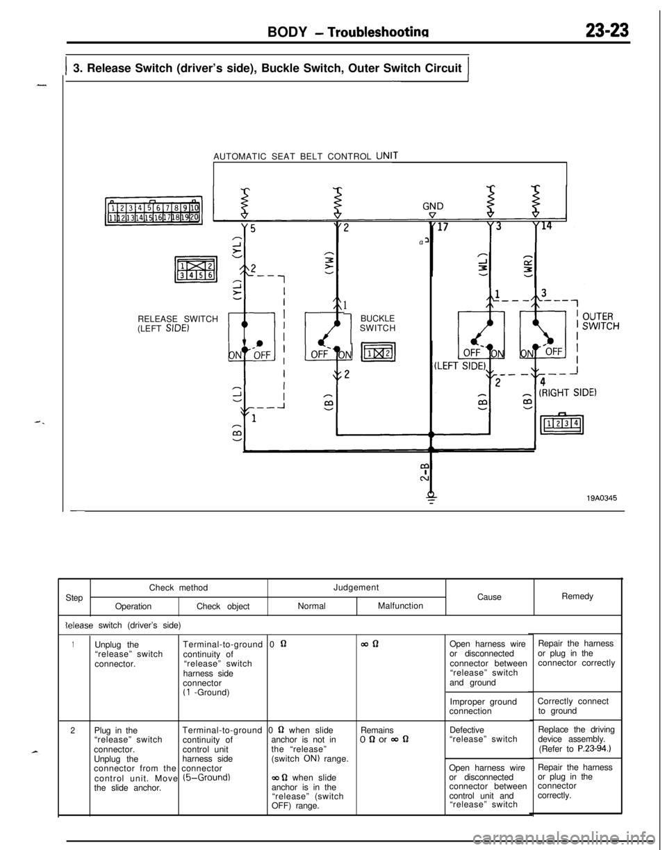
I3. Release Switch (driver’s side), Buckle Switch, Outer Switch CircuitI-1AUTOMATIC SEAT BELT CONTROL UNI
RELEASE SWITCH
(LEFT SIDE)
1
1BUCKLE
SWITCH
a19A0345
Repair the harness
or plug in the
connector correctly Check method
Step
OperationCheck objectlelease switch (driver’s side)Judgement
CauseRemedy
NormalMalfunction
1Unplug theTerminal-to-ground 0 QmclOpen harness wire
“release” switch
continuity ofor disconnected
connector.“release” switchconnector between
harness side“release” switch
connectorand ground
(1 -Ground)
Improper ground
connectionCorrectly connect
to ground
2Plug in theTerminal-to-ground 0 Q when slideRemainsDefective
“release” switch
continuity ofanchor is not inOQorooQ“release” switch
connector.control unitthe “release”
Unplug theharness side(switch
ON) range.
connector from the connectorOpen harness wire
control unit. Move
(5-Ground)ca g when slideor disconnected
the slide anchor.anchor is in theconnector between
“release” (switchcontrol unit and
OFF) range.“release” switchReplace the driving
device assembly.
(Refer to
P.23-94.1Repair the harness
or plug in the
connector
correctly.
Page 1068 of 1216

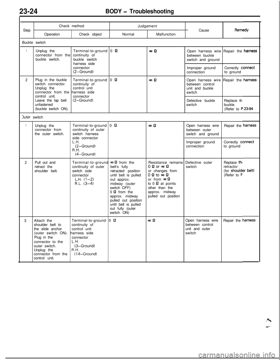
23-24BODY - TroubleshootingCheck method
Step
OperationCheck object
Buckle switchJudgement
Cause
RemINormalMalfunction
1Unplug theTerminal-to-ground 0 Qconnector from the continuity of
buckle switch.
buckle switch
harness side
connector
(2-Ground)
2Plug in the buckle
Terminal-to-ground 0 nswitch connector.
continuity of
Unplug thecontrol unit
connector from the harness side
control unit.
connector
Leave the lap belt
(2-Ground)unfastened
(buckle switch ON).3uter switchOpen harness wire Repair the
between buckle
switch and ground
Improper groundCorrectly
cconnectionto ground
Open harness wire Repair the
between control
unit and buckle
switch
Defective buckleReplace th
switchbuckle.
(Refer to
F
1Unplug theTerminal-to-ground 0 QwflOpen harness wire
Repair the
connector fromcontinuity of outer
between outer
the outer switch.switch harness
switch and ground
side connectorL.H.Improper groundCorrectly
c(2-Ground)connectionto groundR.H.(4-Ground)
2Pull out andTerminal-to-ground 00 0 from theResistance remains Defective outerReplace thl
retract thecontinuity of outerbelt’s fullyOgorconswitchretractor
shoulder belt.switch sideretracted positionor changes from(for should1connectoruntil belt is pulledofltocon(Refer to FL.H. (l-2)out approx.or from 00 62R.L. (3-4)midway (outerto 0 62 at points
switch OFF)other than the
0
0 from theapprox. midway
approx. midwaypulled out position
pulled out position
until belt is pulled
out fully (outer
switch ON)
3Attach theTerminal-to-ground 0
62wdlOpen harness wire
Repair the
shoulder belt tocontinuity ofbetween control
the slide anchorcontrol unitunit and outer
(outer switch ON). harness sideswitch
Plug in the
connector
connector to theL.H.
outer switch.
(3-Ground)Unplug theR.H.connector from the(I 4-Ground)control unit.
Page 1069 of 1216
BODY - Troubleshootinn23-254. Door Latch Switch, Fasten Switch, Release Switch (passenger’s side) Circuit
_-AUTOMATIC SEAT BELT CONTROL UNIT
I,
-- -----_ -"4 "21I
ifsII
II
IIFASTEN
I
ISWITCHI
II(RIGHT
SIDE)
,,6 -4,lI--_ _--_----JI
5 2sI
I7,~-15,L--- _____ --J
8
m
I
Page 1072 of 1216

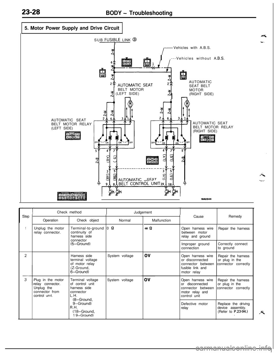
23-28BODY - Troubleshooting5. Motor Power Supply and Drive Circuit
AUTOMATIC SEAT
BELT MOTOR RELAY
(LEFT SIDE)SUB
FUSI;LE LINK @
r-Vehicles with A.B.S.
I,---Vehicles without A
AUTOMATIC
SEAT BELT
BELT MOTOR
2 (LEFT SIDE). .nI nMOTOR
(RIGHT SIDE)
AIITnhAATlr CFAT r!AUTOMATIC SEAT
BELT MOTOR RELAY
(RIGHT SIDE)1310344
Step
1
TCheck method
Judgement
OperationCheck object
Normal
Unplug the motorTerminal-to-ground 0
62relay connector.continuity of
harness side
connector
(5-Ground)Harness side
terminal voltage
of motor relay
(Z-Ground,
6-Ground)System voltage
Plug in the motorTerminal voltage
System voltage
relay connector.of control unit
Unplug theharness side
connector from
connector
control
unit.L.H.(8-Ground,g-Ground)R.H.(18-Ground,1 g--Ground)Malfunction
WQ
ov
ov
TCauseRemedy
Open harness wire
Repair the harness
between motor
relay and ground
Improper groundCorrectly connect
connectionto ground
Open harness wire
Repair the harness
or disconnectedor plug in the
connector between connector correctly
fusible link and
motor relay
Open harness wire
Repair the harness
or disconnectedor plug in the
connector between connector correctly
motor relay and
control unit
Defective motor
relayReplace the driving
device assembly.
(Refer to
P.23-94.),
Page 1073 of 1216
.-
BODY - Troubleshooting
AUTOMATIC SEAT BELT COMPONENTS LOCATION
WA0734
NameSymbolNameSymbolAutomatic seat belt control unit
CFasten switchAAutomatic seat belt motor
Automatic seat belt motor relay
Buckle switch
BuzzerDoor latch switch
EKey reminder switchI
DOuter switchF
GSeat belt warning lightJ
KRelease switchH
B--
A
P
(:0
Page 1074 of 1216
23-30BODY - TroubleshootingAutomatic seat
belt control unit
Ovter switch
19A034(
IAutomatic seat
1680745
reminder switch
Page 1110 of 1216

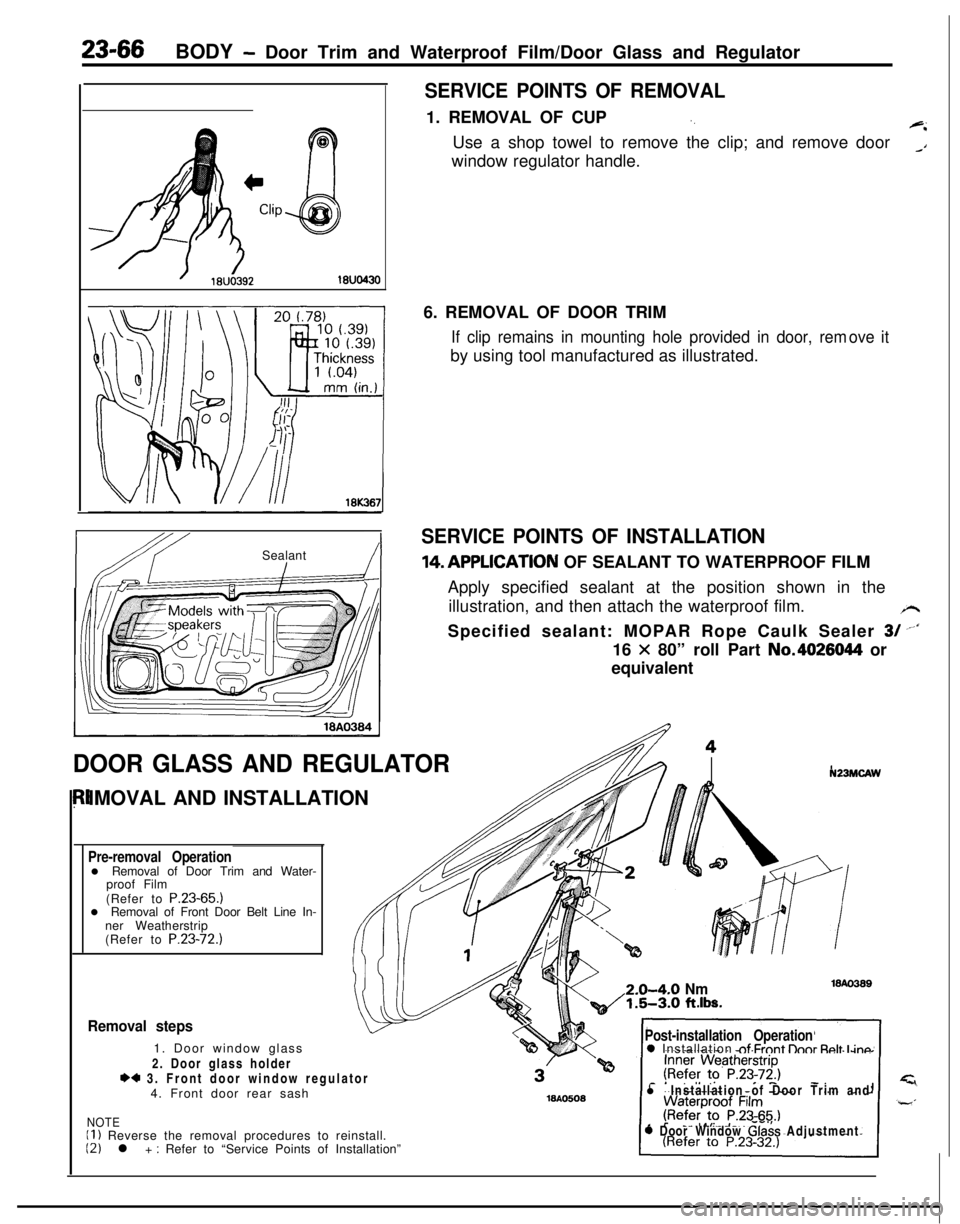
23-66BODY - Door Trim and Waterproof Film/Door Glass and Regulator
SERVICE POINTS OF REMOVAL1. REMOVAL OF CUP
‘.+iUse a shop towel to remove the clip; and remove door
_Awindow regulator handle.
IbY ISealant!I6. REMOVAL OF DOOR TRIM
If clip remains in mounting hole provided in door, remby using tool manufactured as illustrated.ove it
SERVICE POINTS OF INSTALLATION14,APPLlCATlON OF SEALANT TO WATERPROOF FILM
Apply specified sealant at the position shown in the
illustration, and then attach the waterproof film.
/rSpecified sealant: MOPAR Rope Caulk Sealer
3/ --‘I16
X 80” roll Part No.4026044 or
equivalent
DOOR GLASS AND REGULATORIMOVAL AND INSTALLATION
Pre-removal Operationl Removal of Door Trim and Water-
proof Film
(Refer to P.23-65.)
l Removal of Front Door Belt Line In-
ner Weatherstrip
(Refer to P.23-72.)
N23MCAW2.0-4-O
Nm1.5-3.0 ft.lbs.
Removal steps1. Door window glass
2. Door glass holder
*4 3. Front door window regulator
4. Front door rear sash
NOTEII ) Reverse the removal procedures to reinstall.12) l + : Refer to “Service Points of Installation”
Post-installation Operation0 Installation nf Frnnt lhnr Rnlt I inn
l Installation of Door Trim and
0 Door Window Glass Adjustment