Page 1047 of 1216
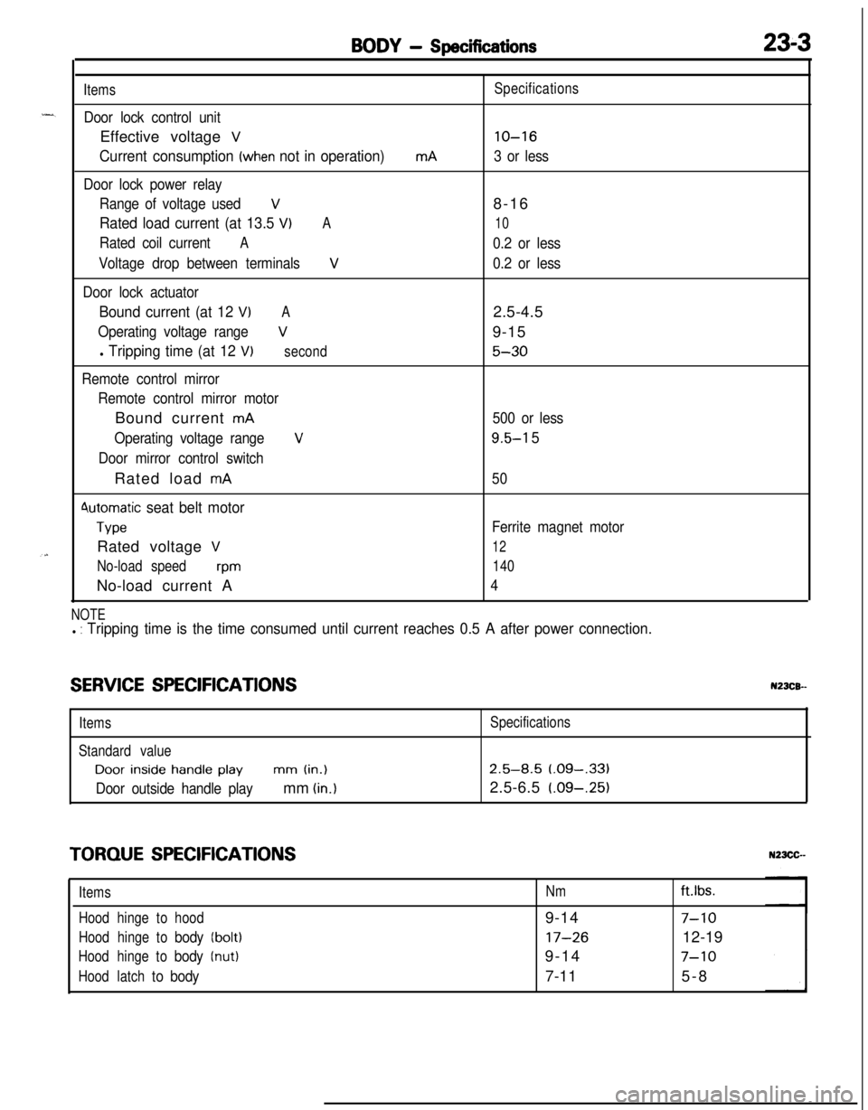
BODY - Specifications23-3
Items
Door lock control unitEffective voltage
V
Current consumption (when not in operation)
Door lock power relay
Range of voltage used
V
Rated load current (at 13.5 VIA
Rated coil currentA
Voltage drop between terminalsV
Door lock actuator
Bound current (at 12 VIA
Operating voltage rangeV
l Tripping time (at 12 V)second
Remote control mirror
Remote control mirror motorBound current
mA
Operating voltage range
V
Door mirror control switchRated load
mA
4utomatic seat belt motor
TypeRated voltage
V
No-load speedwmNo-load current A
mASpecifications
lo-16
3 or less8-16
10
0.2 or less
0.2 or less2.5-4.5
9-15
5-30
500 or less
9.5-l 5
50
Ferrite magnet motor
12
140
4
NOTEl : Tripping time is the time consumed until current reaches 0.5 A after power connection.
SERVICE SPECIFICATIONSN23CB--
ItemsSpecifications
Standard valueDoor
inside handle playmm (in.)2.5-8.5 (.09-,331
Door outside handle playmm (in.)2.5-6.5 (.09-.25)
TORQUE SPECIFICATIONS
ItemsNmft.lbs.
Hoodhingetohood9-14
7-10
Hoodhingetobody(bolt)17-2612-19
Hoodhingetobody(nut)9-147-10
Hoodlatchtobody7-115-8
Page 1048 of 1216
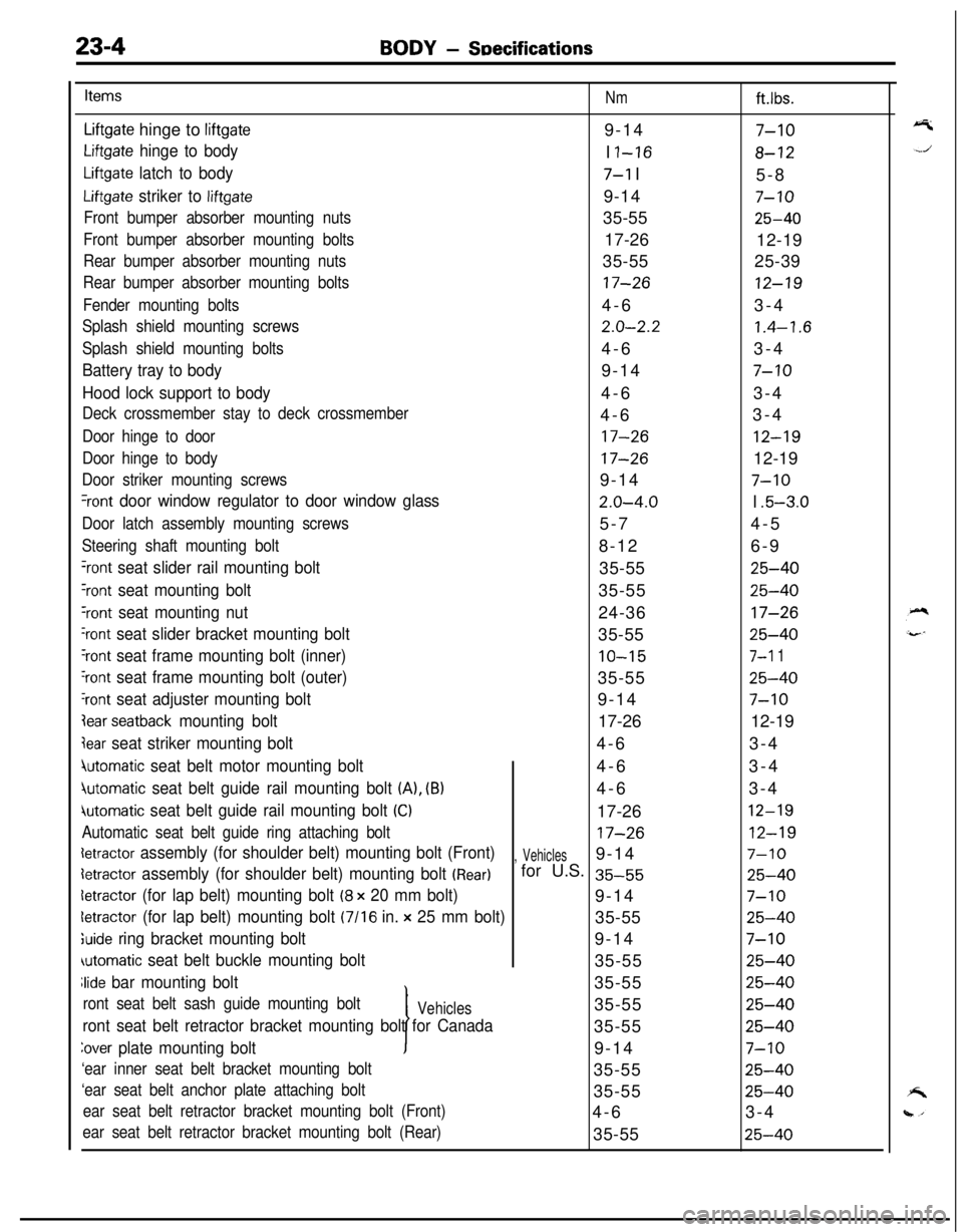
23-4BODY - SDecifications
Items
Nmft.lbs.
Liftgate hinge to liftgate9-147-10
Liftgate hinge to bodyI I-168-12
Liftgate latch to body7-l I
5-8
Liftgate striker to liftgate9-147-10
Front bumper absorber mounting nuts35-5525-40
Front bumper absorber mounting bolts17-26
12-19
Rear bumper absorber mounting nuts35-5525-39
Rear bumper absorber mounting bolts17-2612-19
Fender mounting bolts4-63-4
Splash shield mounting screws2.0-2.21.4-1.6
Splash shield mounting bolts4-63-4
Battery tray to body9-147-10
Hood lock support to body4-63-4
Deck crossmember stay to deck crossmember4-63-4
Door hinge to door17-2612-19
Door hinge to body17-2612-19
Door striker mounting screws9-147-10
%ont door window regulator to door window glass2.0-4.0I .5-3.0
Door latch assembly mounting screws5-74-5
Steering shaft mounting bolt8-126-9
‘rant seat slider rail mounting bolt35-5525-40
Yont seat mounting bolt35-5525-40
‘rant seat mounting nut24-3617-26
‘rant seat slider bracket mounting bolt35-5525-40
‘rant seat frame mounting bolt (inner)10-157-l 1
‘rant seat frame mounting bolt (outer)35-5525-40
‘rant seat adjuster mounting bolt9-147-10
lear seatback mounting bolt17-2612-19
jear seat striker mounting bolt4-63-4
4utomatic seat belt motor mounting bolt4-63-4
jutomatic seat belt guide rail mounting bolt (A), (B)4-63-4
iutomatic seat belt guide rail mounting bolt (Cl17-2612-19
Automatic seat belt guide ring attaching bolt17-2612-19
detractor assembly (for shoulder belt) mounting bolt (Front), Vehicles9-147-10
detractor assembly (for shoulder belt) mounting bolt (Rear)for U.S. 35-5525-40
detractor (for lap belt) mounting bolt (8 x 20 mm bolt)9-147-10
letractor (for lap belt) mounting bolt (7116 in. x 25 mm bolt)35-5525-40
;uide ring bracket mounting bolt9-147-10
automatic seat belt buckle mounting bolt35-5525-40
Jide bar mounting bolt
I35-55
25-40
ront seat belt sash guide mounting boltVehicles35-5525-40
ront seat belt retractor bracket mounting bolt for Canada35-5525-40
Zover plate mounting bolt9-147-10
‘ear inner seat belt bracket mounting bolt35-5525-40
‘ear seat belt anchor plate attaching bolt35-5525-40
ear seat belt retractor bracket mounting bolt (Front)4-63-4
ear seat belt retractor bracket mounting bolt (Rear)35-5525-40
Page 1059 of 1216
c
BODY - Troubleshooting2345
IUZZER < Vechicles for Canada >
CIRCUIT DIAGRAMIGNITION
J/B0
10A
c-37x
El34
SEAT BELT
TIMER
'ITCH(IG1)
1OA
y4 C-52
/
WHEN KEYIS REMOVED4,
II
I
I
I
I
I
IIII
I
I
II
I
I
I
I
IIIIIII
.
6
I=3?;IWELTBUZZER
\\ (B)
"4
J/B\I
"5 c-54
WITH
R!Ei&-ESTEM
DIODE
E-52
91FRONT DOOR SWITCH
cu(LEFT SIDE)
N23EBABa
KX35-AC-UlblB-NC
Page 1060 of 1216
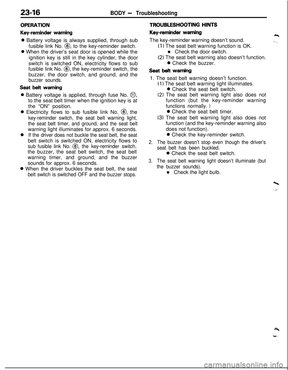
23-16BODY - Troubleshooting
OPERATION
Key-reminder warning0 Battery voltage is always supplied, through sub
fusible link No.
@, to the key-reminder switch.0 When the driver’s seat door is opened while the
ignition key is still in the key cylinder, the door
switch is switched ON, electricity flows to sub
fusible link No.
0, the key-reminder switch, the
buzzer, the door switch, and ground, and the
buzzer sounds.
Seat belt warning0 Battery voltage is applied, through fuse No.
0,to the seat belt timer when the ignition key is at
the “ON” position.0 Electricity flows to sub fusible link No. @, the
key-reminder switch, the seat belt warning light,
the seat belt timer, and ground, and the seat beltwarning light illuminates for approx. 6 seconds.0
If the driver does not buckle the seat belt, the seatbelt switch is switched ON, electricity flows to
sub fusible link No. @, the key-reminder switch,the buzzer, the seat belt switch, the seat belt
warning timer, and ground, and the buzzer
sounds for approx. 6 seconds.0 When the driver buckles the seat belt, the seat
belt switch is switched OFF and the buzzer stops.
TROUBLESHOOTING HINTS
Key-reminder warningThe key-reminder warning doesn’t sound.
(1) The seat belt warning function is OK.
l Check the door switch.
(2) The seat belt warning also doesn’t function.0 Check the buzzer.
Seat belt warning1. The seat belt warning doesn’t function.
(1) The seat belt warning light illuminates.0 Check the seat belt switch.
(2) The seat belt warning light also does not
function (but the key-reminder warning
functions normally. 10 Check the seat belt timer.
(3) The seat belt warning light also does not
function (and the key-reminder warning also
does not function).0 Check the key-reminder switch.
2.The buzzer doesn’t stop even though the driver’s
seat belt has been buckled.0 Check the seat belt switch.
3.The seat belt warning light doesn’t illuminate (but
the buzzer sounds).l Check the light bulb.
’ I
Page 1061 of 1216
BODY - Troubleshootina234 7AUTOMATIC
SEAT BELT N23EBGD
CIRCUIT DIAGRAM
IGNSW1
b
c
ION'H (IGl)
3-BW
I
COMBINATION
METER2
L
:I
3
D-06 i
E
WHEN KE
l%OVEO
14
-----1
I
I
I
I
f51
II
>
I
I:
I
I52
1
I
I13 ;----
1OAb10A\,7“4
4C-52 m
AUTOMATIC
SEAT BELT
CONTROL UNIT
P2
St1ELT
M6-AC-Ul6lZ-NCm
.---
.,*i
i
6
c:
13
W'HEN KEY&TALLEDm
!
43cu
Page 1062 of 1216
23-18BODY - Troubleshooting
AUTOMATIC SEAT BELT
SUB FUSIBLE LINK QCONTROL UNITIE-41
-------____---__-----~-~--~~~-----I1
2E-46
I
I
I
I
‘1 II I
I II II I
I II I
I I
I II I
I I
I II I
I I
I II I
I I
_----------
1
sL
E-57
t
--A37t
1 :
1
I
I
I
IDOORLATCH 7-I
TF;W;H cLo8'I
SIDE), IE-51
9+3 I
125!?‘pIcr.3,,7 f----
m
I
AUTOMATIC SEIBELT MOTOR R
!3
(RIGHT SIDE)
ON$ .aOFF
I I
1 ..
I I
I I
jI I
I I
I I
i I------ I
I
I
I
I
__----J
\/I
‘,“piaq
E!G__ --------3 5
slx
3 A0
++1
4
:
c_---
2.
L----------------:1--1
2
15_---_---_____---~--
II
ISk3m
11
ICL-,,7L---- ,,
m
.h7
c-51 --J/B
LL
, 2 3 4 C-54 “5
56678m
SIDE) AUTOMATIC SEAT BELTE-07CONTROL UNIT
E-41
AUTOMATIC SEAT BELTCONTROL UNITE-41
&- Remark=*The connectqr,indicated,QYthe x SYmbOl is aPPIicat)le to
vehicles with ABS.
Page 1063 of 1216
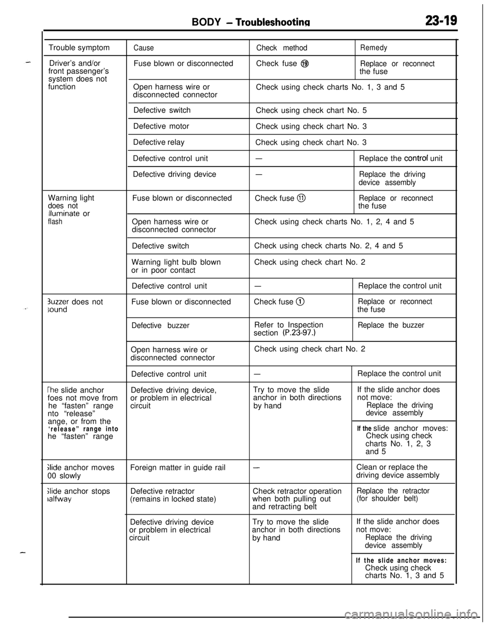
BODY - Troubleshootinn2349Trouble symptom
Driver’s and/or
front passenger’s
system does not
function
CauseFuse blown or disconnected
Open harness wire or
disconnected connectorCheck methodRemedyCheck fuse
@IReplace or reconnectthe fuse
Check using check charts No. 1, 3 and 5
Defective switch
Defective motor
Defective relay
Defective control unit
Defective driving deviceCheck using check chart No. 5
Check using check chart No. 3
Check using check chart No. 3
-Replace the control unit
-Replace the driving
device assemblyWarning light
does notlluminate or
flashFuse blown or disconnected
Open harness wire or
disconnected connectorCheck fuse
@IReplace or reconnectthe fuse
Check using check charts No. 1, 2, 4 and 5
Defective switch
Warning light bulb blown
or in poor contactCheck using check charts No. 2, 4 and 5
Check using check chart No. 2
3uzzer does notsoundDefective control unit
Fuse blown or disconnected
Defective buzzer
-Check fuse @
Refer to Inspection
section
(P.23-97.)Replace the control unit
Replace or reconnectthe fuse
Replace the buzzerOpen harness wire or
disconnected connectorCheck using check chart No. 2
Defective control unit
-Replace the control unit
The slide anchorDefective driving device,Try to move the slideIf the slide anchor does
foes not move fromor problem in electricalanchor in both directionsnot move:
he “fasten” rangecircuitby hand
Replace the drivingnto “release”device assemblyange, or from the
‘release”range intoIf the slide anchor moves:
he “fasten” rangeCheck using check
charts No. 1, 2, 3
and 5
Glide anchor moves
00 slowly
Slide anchor stopsralfwayForeign matter in guide rail
Defective retractor
(remains in locked state)
-Clean or replace the
driving device assembly
Check retractor operation
Replace the retractorwhen both pulling out(for shoulder belt)and retracting belt
Defective driving deviceTry to move the slide
or problem in electricalanchor in both directions
circuit
by handIf the slide anchor does
not move:
Replace the driving
device assemblyIf the slide anchor moves:
Check using check
charts No. 1, 3 and 5
Page 1064 of 1216
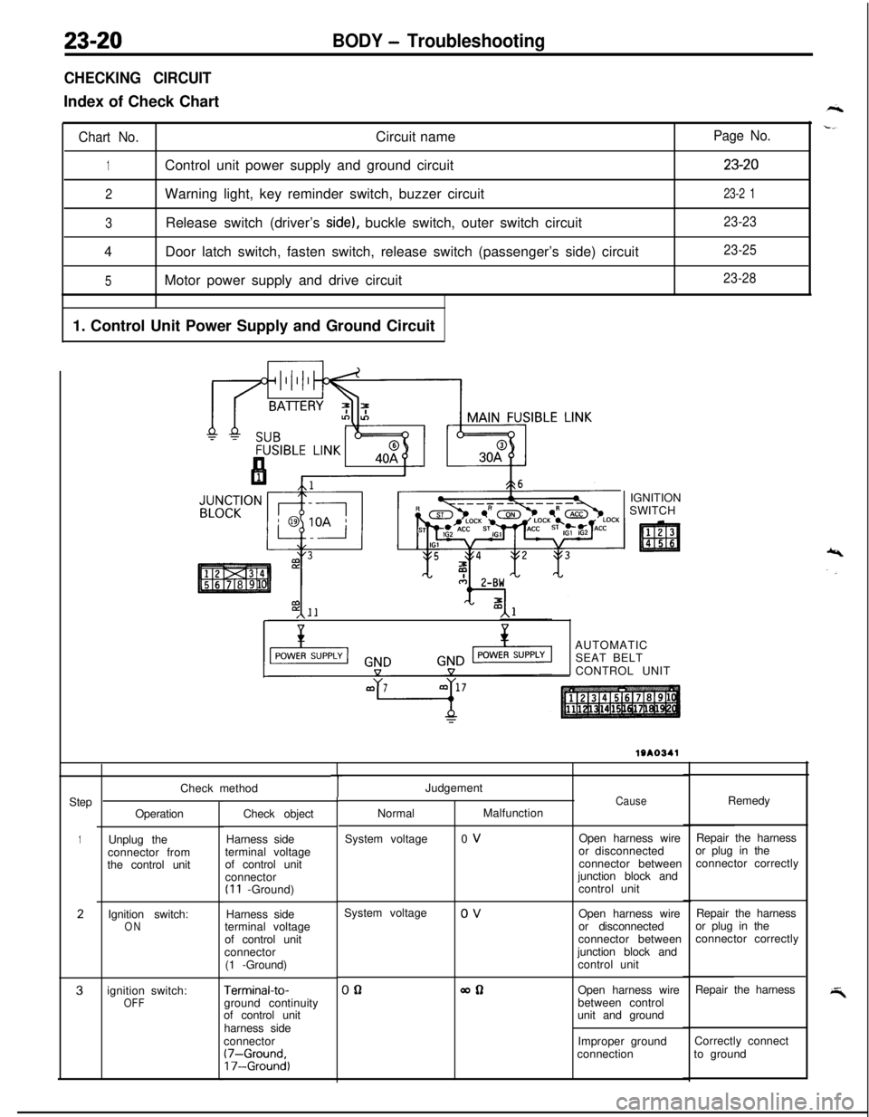
23-20BODY - Troubleshooting
CHECKING CIRCUITIndex of Check Chart
Chart No.Circuit name
1Control unit power supply and ground circuit
2Warning light, key reminder switch, buzzer circuit
3Release switch (driver’s side), buckle switch, outer switch circuit
4Door latch switch, fasten switch, release switch (passenger’s side) circuit
5Motor power supply and drive circuit
1. Control Unit Power Supply and Ground Circuit
Page No.
23-20
23-2 1
23-23
23-25
23-28IGNITION
SWITCH
,\--AUTOMATIC
SEAT BELT
CONTROL UNIT
Step
1
2
3Check method
Operation
Unplug the
connector from
the control unit
Ignition switch:
ONignition switch:
OFFCheck object
Harness side
terminal voltage
of control unit
connector
(I 1 -Ground)
Harness side
terminal voltage
of control unit
connector
(1 -Ground)
Terminal-to-ground continuity
of control unit
harness side
connector
(7-Ground,17-Ground)
TJudgement
NormalMalfunction
System voltage0 VCauseOpen harness wire
or disconnected
connector between
junction block and
control unitRemedy
Repair the harness
or plug in the
connector correctly
System voltage
0 V
Open harness wire
or disconnected
connector between
junction block and
control unitRepair the harness
or plug in the
connector correctly
00allOpen harness wire
between control
unit and groundRepair the harness
Improper groundCorrectly connect
connectionto ground