1991 MITSUBISHI ECLIPSE sensor
[x] Cancel search: sensorPage 282 of 1216
7-34 COOLINGWater Hose and Water Pipe <2.0L DOHC Engine (Turbo)>/Engine Coolant Temperature- Gauge Unit. Engine Coolant Temoerature Sensor and Enoine Coolant Temoerature Switch
05A0026
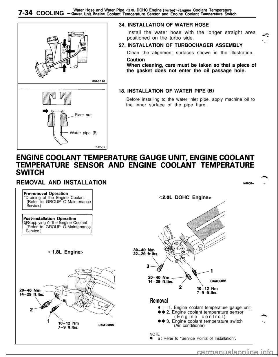
05K55734. INSTALLATION OF WATER HOSE
Install the water hose with the longer straight area
positioned on the turbo side.
27. INSTALLATION OF TURBOCHAGER ASSEMBLY
Clean the alignment surfaces shown in the illustration.
Caution
When cleaning, care must be taken so that a piece of
the gasket does not enter the oil passage hole.
18. INSTALLATION OF WATER PIPE
(B)Before installing to the water inlet pipe, apply machine oil to
the inner surface of the pipe flare.
ENGINE COOLANT TEMPERATURE GAUGE UNIT, ENGINE COOLANT
TEMPERATURE SENSOR AND ENGINE COOLANT TEMPERATURE
SWITCHREMOVAL AND INSTALLATION
N070%-
Pre-removal Operation
*Draining of the Engine Coolant
(Refer to GROUP O-Maintenance
Service.)@Supplying of the Engine Coolant
(Refer to GROUP O-Maintenance
< 1.8L Engine>
20-4014-291
’lo-12 Nm7-9 ft.lbs.04AOO99<2.0L DOHC Engine>10112 Nm
7-9 ft.lbs.
Removal
l +1. Engine coolant temperature gauge unit
++ 2. Engine coolant temperature sensor
(Engine control)
*4 3. Engine coolant temperature switch(Air conditioner)
NOTEl a : Refer to “Service Points of Installation”.
Page 283 of 1216
COOLINGEngine Coolant Temperature Gauge Unit, Engine Coolant- TemDerature Sensor and Enaine Coolant Temperature Switch7-35
.---
Sensor04GO033
0400032
1c0010
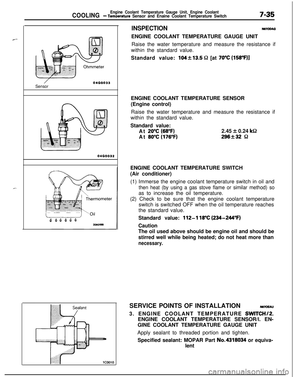
INSPECTIONNomDM3ENGINE COOLANT TEMPERATURE GAUGE UNIT
Raise the water temperature and measure the resistance if
within the standard value.
Standard value:
104213.5 52 [at 70°C (158OF)lENGINE COOLANT TEMPERATURE SENSOR
(Engine control)
Raise the water temperature and measure the resistance if
within the standard value.
Standard value:
At
20°C (68°F)2.45 + 0.24 k&
At
80°C (176°F)296f32 8ENGINE COOLANT TEMPERATURE SWITCH
(Air conditioner)
(1) Immerse the engine coolant temperature switch in oil and
then heat (by using a gas stove flame or similar method) soas to increase the oil temperature.
(2) Check to be sure that the engine coolant temperature
switch is switched OFF when the oil temperature reaches
the standard value.
Standard value:
112-l 18°C (234-244°F)Caution
The oil used above should be engine oil and should be
stirred well while being heated; do not heat more than
necessary.SERVICE POINTS OF INSTALLATION
NO7OEAU3. ENGINE COOLANT TEMPERATURE
SWITCHI2.ENGINE COOLANT TEMPERATURE SENSOR/l. EN-
GINE COOLANT TEMPERATURE GAUGE UNIT
Apply sealant to threaded portion and tighten.
Specified sealant: MOPAR Part No.4318034 or equiva-
lent
Page 303 of 1216

-
ENGINE - Specifications9-19Items
Oil sprocketpump
Silent shaft sprocket
Timing belt tensioner nut or bolt
Timing belt rear cover (upper)
(lower)
Oil drivenpump gear
Front case
Connecting rod bearing cap
Crankshaft bearingcap
<2.0L DOHC Engine>
Engine mount bracket to bracket nut or bolt
Engine cooler pipe to engine front case
Exhaust pipe to exhaust manifold (Turbo)
Oil return pipe to oil pan (Turbo)
Oil screen nut or bolt
Centermember installation bolt
Oil pipe to engine (Turbo)
Rocker cover
Center cover
Heat protector to exhaust manifold
Exhaust manifold to turbocharger(Turbo)
Intake manifold stay bolt
Cylinder head bolt
Crankshaft pulley
Oil sprocketpump
Silent shaft sprocket
Auto tensioner
Timing belt tensioner pulley
Timing belt idle pulley
Timing belt rear cover
Oil drivenpump gear
Front case
Engine oil cooler mounting nut
Eye bolt (Engine oil cooler side)
Engine oil hose mounting bolt
Engine oil feed hose assembly to Feed/Return tube assembly
Engine oil return hose assembly to Feed/Return tube assembly
Feed/Return tube assembly to oil filter bracket
Eye bolt (Oil filter bracket side)
Crankshaft angle sensor
Throttle body stayNm
ft.lbs.
34-4026-29
34-4025-29
22-3016-22
IO-127-9
12-159-11
34-4025-29
15-18
11-1332-3524-25
50-5537-39
17-26
12-19
40-4529-33
40-6029-43
8-106-7
15-2211-16
80-l 0058-72
14-19
10-142.5-3.52-3
2.5-3.52-3
12-15
9-l 155-65
40-47
25-3018-22
90-10065-72
20-3014-22
50-6036-43
43-49
31-35
20-2714-2043-55
31-4034-42
25-30
10-127-9
34-4025-29
20-2214-16
8-126-9
30-3522-25
3-52-4
40-5029-36
40-5029-36
3-52-4
40-4529-33
IO-137-9
15-2211-16SEALANTS AND ADHESIVES
NOSCE-.Items
Specified sealant
“. _
SemiWrcularMOPAR Part No.4318034Rocker cover
<2.0L
1(No.4318034No.1141~1
1 Oil pan1No.MD997110I
Page 315 of 1216
ENGINE <1.8L Engine> - Engine Assembly9-31
ENGINE ASSEMBLY
. REMOVAL AND INSTALLATION
N69SA-APre-removal Operation
@Eliminating Fuel Pressure in Fuel Line
(Refer to GROUP 14-Service AdjustmentProcedures.)@Removal of Engine HoodeDraining of Engine Coolant
(Refer to GROUP O-Maintenance Service.)
l Removal of the Transaxle Assembly(Refer to GROUP 21 -Transaxle Assembly.)
*Removal of the Radiator
(Refer to GROUP 7-Radiator.)
Post-installation Operation
@Installation of the Radiator
(Refer to GROUP 7-Radiator.)
l Installation of the Transaxle Assembly(Refer to GROUP 21 -Transaxle Assembly.)
@Refilling of Engine Coolant
(Refer to GROUP O-Maintenance Service.)
l Installation of Engine Hood4-6 Nm
“7
/61OlA05664-6 Nm
3-4
ft.lbs.
\
16
/io1\4-6Nm164-6Nm193-4ft.lbs.
173-4ft.lbs.OlA0643Removal steps
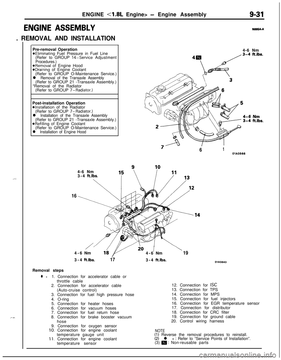
l +1. Connection for accelerator cable or
throttle cable
2. Connection for accelerator cable
(Auto-cruise control)
3. Connection for fuel high pressure hose
4. O-ring
5. Connection for heater hoses
6. Connection for vacuum hoses
7. Connection for fuel return hose
8. Connection for brake booster vacuum
hose
9. Connection for oxygen sensor
10. Connection for engine coolant
temperature gauge unit
11. Connection for engine coolant
temperature sensor12. Connection for
ISC13. Connection for TPS
14. Connection for MPS
15. Connection for fuel injectors
16. Connection for EGR temperature sensor
17. Connection for distributor
18. Connection for CRC filter
19. Connection for ground cable
20. Control wiring harness
NOTE(1) Reverse the removal procedures to reinstall.(2) l + : Refer to “Service Points of Installation”.
(3) m : Non-reusable parts
Page 320 of 1216
9-36ENGINE
CYLINDER HEAD GASKET
REMOVAL AND INSTALLATION4-6 Nm
73-4 ft.lbs.
NWJA-A
Pre-removal Operationl Eliminating Fuel Pressure in Fuel
Line(Refer to GROUP
14-Service Ad-
justment Procedures.)*Draining of En
ine Coolant
(Refer to GRO9P -/-Service Adjust-ment Procedures.)
(Refer to GROUP
7-Service Adjust-~~~~~~~n
?*
29?i
8
30-46 Nm
22-29 ft.lbs.
60-80 ium43-58 ftlbs.25
iy 24 \\3-4
ftlbs./2227 26
Removal steps
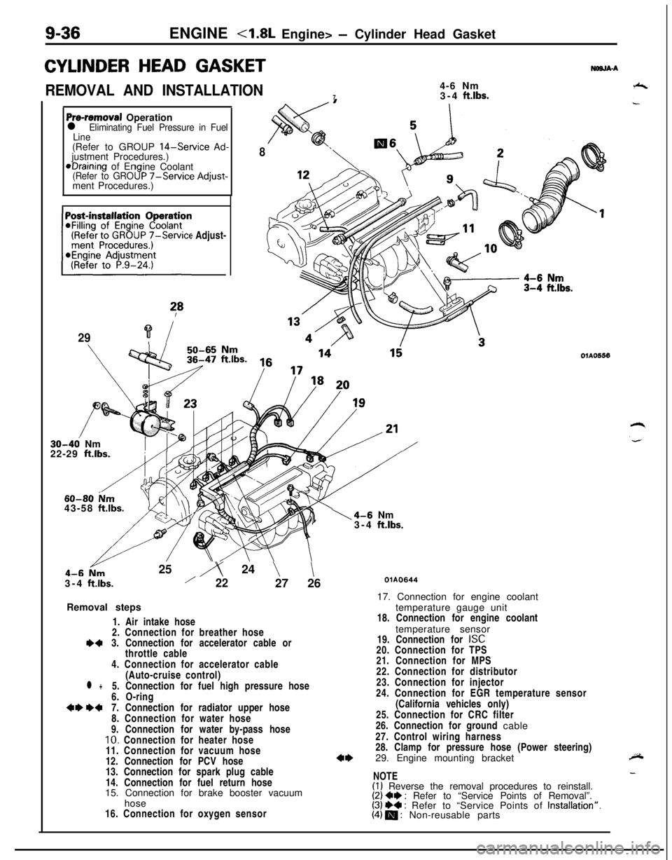
1. Air intake hose
2. Connection for breather hose
I)43. Connection for accelerator cable or
throttle cable
4. Connection for accelerator cable
(Auto-cruise control)
l +5. Connection for fuel high pressure hose
6. O-ring
+e W7. Connection for radiator upper hose
8. Connection for water hose
9. Connection for water by-pass hose
10. Connection for heater hose
11. Connection for vacuum hose
12. Connection for PCV hose
13. Connection for spark plug cable
14. Connection for fuel return hose
15. Connection for brake booster vacuum
hose
16. Connection for oxygen sensor
1\4-6 Nm
3-4 ftlbs.
OlAO556
QlAO64417. Connection for engine coolant
temperature gauge unit
18. Connection for engine coolant
temperature sensor
19. Connection for
ISC20. Connection for TPS
21. Connection for MPS
22. Connection for distributor
23. Connection for injector
24. Connection for EGR temperature sensor
(California vehicles only)
25. Connection for CRC filter
26. Connection for ground cable
27. Control wiring harness
28. Clamp for pressure hose (Power steering)
29. Engine mounting bracket
NOTE
(I) Reverse the removal procedures to reinstall.(2) Ce : Refer to “Service Points of Removal”.(3) ++ : Refer to “Service Points of Installation”.(4) m : Non-reusable parts
Page 365 of 1216
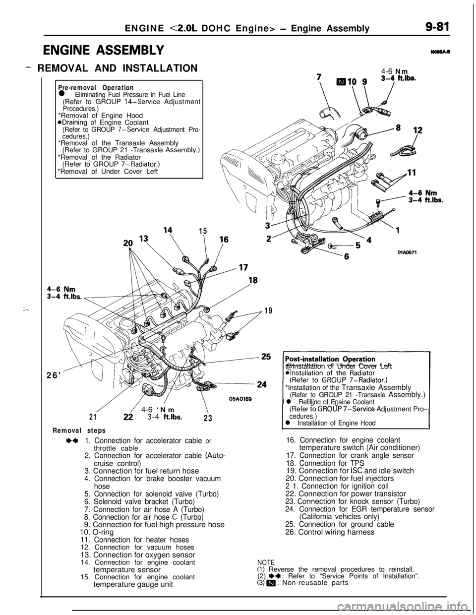
ENGINE <2.0L DOHC Engine> - Engine Assembly
ENGINE ASSEMBLY
- REMOVAL AND INSTALLATION
;-
Pre-removal Operationl Eliminating Fuel Pressure in Fuel Line(Refer to GROUP 14-Service AdjustmentProcedures.)*Removal of Engine Hood
@Draining of Engine Coolant(Refer to GROUP 7-Service Adjustment Pro-
cedures.)*Removal of the Transaxle Assembly
(Refer to GROUP 21 -Transaxle Assembly.)
*Removal of the Radiator
(Refer to GROUP 7-Radiator.)
*Removal of Under Cover Left
26'
15
I4-6 Nm\I /MAO571
19@Installation of Under Cover Left
*Installation of the Transaxle Assembly
(Refer to GROUP 21 -Transaxle Assembly.)
I l Refilling of Enaine Coolant
/22/ 4-6 ‘Nm\213-4 ftlbs.23
Removal steps
~~1. Connection for accelerator cable orthrottle cable
2. Connection for accelerator cable (Auto-
cruise control)3. Connection for fuel return hose
4. Connection for brake booster vacuum
hose
5. Connection for solenoid valve (Turbo)
6. Solenoid valve bracket (Turbo)
7. Connection for air hose A (Turbo)
8. Connection for air hose
C (Turbo)9. Connection for fuel high pressure hose
10. O-ring11. Connection for heater hoses12. Connection for vacuum hoses
13. Connection for oxygen sensor
14. Connection for engine coolant
temperature sensor
15. Connection for engine coolant
temperature gauge unit(Refer
t’o GROUP 7-Service Adjustment Pro-cedures.)l Installation of Engine Hood‘I
16. Connection for engine coolanttemperature switch (Air conditioner)
17. Connection for crank angle sensor
18. Connection for TPS19. Connection for
ISC and idle switch
20. Connection for fuel injectors
2 1. Connection for ignition coil22. Connection for power transistor
23. Connection for knock sensor (Turbo)
24. Connection for EGR temperature sensor
(California vehicles only)
25. Connection for ground cable26. Control wiring harness
NOTE(I) Reverse the removal procedures to reinstall.
(2) e+ : Refer to “Service Points of Installation”.(3) m : Non-reusable parts
Page 368 of 1216
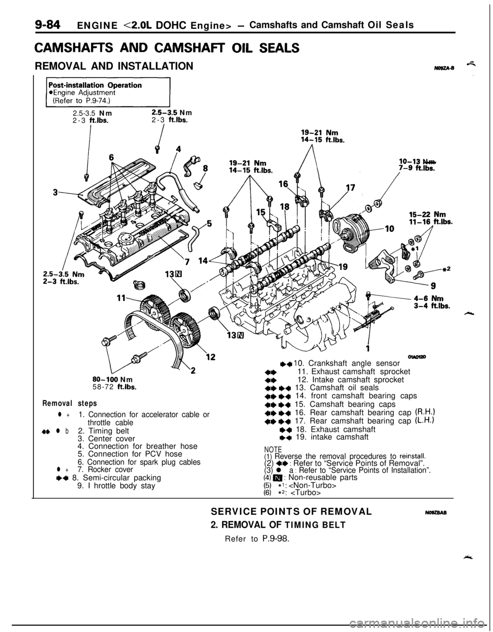
9-84ENGINE <2.0L DOHC Engine> -Camshafts and Camshaft Oil Seals
CAMSHAFR AND CAMSHAR OIL SEALSREMOVAL AND INSTALLATION
No8u-s
ppEJ=-j2.5-3.5 Nm
2.5-3.5 Nm
2-3 ft.lbs.2-3 ft.lbs.
lo-13 Nm
olmlzo++ 10. Crankshaft angle sensor
a*11. Exhaust camshaft sprocket80-100 Nm4*12. Intake camshaft sprocket
58-72 ftlbs.+e *+ 13. Camshaft oil seals
Removal steps+e e+ 14. front camshaft bearing caps41)
+4 15. Camshaft bearing caps
l +1. Connection for accelerator cable or+e +c 16. Rear camshaft bearing cap (R.H.)
throttle cable+e +4 17. Rear camshaft bearing cap (L.H.)
d+ l b2. Timing belt~~ 18. Exhaust camshaft
3. Center cover+q 19. intake camshaft
4. Connection for breather hose
5. Connection for PCV hose
NOTE
6. Connection for spark plug cables(1) Reverse the removal procedures to reinstall.(2) 4* : Refer to “Service Points of Removal”.l +7. Rocker cover
(3) l a : Refer to “Service Points of Installation”.~~ 8. Semi-circular packing(4) m : Non-reusable parts
9. I hrottle body stay
1:;*I:
SERVICE POINTS OF REMOVAL
No9zsAB
2. REMOVAL OF TIMING BELTRefer to P.9-98.
Page 369 of 1216

ENGINE <2.0L DOHC Engine> -Camshafts and Camshaft Oil Seals9-85Plastic hammer
Intake side
Exhaust side
Jzzl
(22
Slits
11. REMOVAL OF EXHAUST CAMSHAFT SPROCKET/
12. INTAKE CAMSHAFT SPROCKET(1) Using a wrench at the hexagonal part of the camshaft
(to prevent the crankshaft from turning), loosen the
cramshaft sprocket bolt.
(2) Remove the camshaft sprokets.
13. REMOVAL OF CAMSHAFT OIL SEALSRemove the oil seals using a screwdriver or similar tool.
Caution
Take care not to damage front camshaft bearing cap
and camshaft.
14./15./16./17. REMOVAL OF CAMSHAFT BEARfNG CAPS(1) Loosen the bearing cap installation bolts in two or
three steps.
(2) Remove the bearing cap.
NOTEIf the bearing cap is difficult to remove, use a plastic
hammer to gently tap the rear
.part of the camshaft,
and then remove.
SERVICE POINTS OF INSTALLATIONNO92DAB
lg. INSTALLATION OF INTAKE CAMSHAFT/18. EXHAUST
CAMSHAFT(1) Install the camshafts on the cylinder head.
Caution
Be sure not to mistake the intake side and the
exhaust side. There are slits for crank angle sensor
drive in the rear end of the intake camshaft.
NOTEInstall new camshafts using the following procedure.
(1) Remove the rocker arms.
(2) Lay the camshafts on the cylinder head and install
the bearing caps.
(3) Check that the camshaft can be easily turned by
hand.(4) After checking, remove the bearing caps and the
camshafts, and install the rocker arms.