Page 1198 of 1216

EMISSION CONTROL SYSTEMS - Specifications
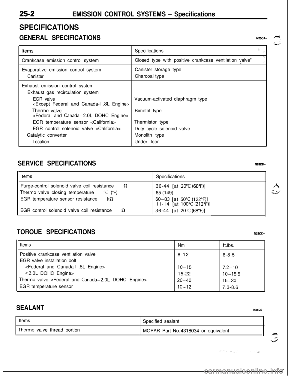
SPECIFICATIONS
GENERAL SPECIFICATIONSN25CA-ItemsSpecifications
.,:..rCrankcase emission control systemClosed type with positive crankcase ventilation valve”I
‘:Evaporative emission control systemCanister storage type
CanisterCharcoal type
Exhaust emission control system
Exhaust gas recirculation system
EGR valveVacuum-activated diaphragm type
.8L Engine>
Therm0 valveBimetal type
EGR temperature sensor Thermistor type
EGR control solenoid valve
Duty cycle solenoid valve
Catalytic converterMonolith type
LocationUnder floor
SERVICE SPECIFICATIONSN25CB-
ItemsSpecifications
Purge-control solenoid valve coil resistance
&236-44 [at 20°C (68”F)I
Therm0 valve closing temperature“C (“F)65 (149)
EGR temperature sensor resistance
kQ60-83 [at 50°C (122”F)]11-14 [at
100°C (212”F)]EGR control solenoid valve coil resistance
S236-44 [at 20°C (68”F)]
TORQUE SPECIFICATIONSN25CC-
ItemsPositive crankcase ventilation valve
EGR valve installation bolt
.8L Engine>
<2.0L DOHC Engine>
Therm0 valve
EGR temperature sensor
Nmftlbs.8-12
6-8.5
IO-157.2-1015-22
10-15.5
20-4015-30
10-127.3-8.6
SEALANT
Items
Therm0 valve thread portionSpecified sealant
MOPAR Part No.4318034 or equivalent
Page 1207 of 1216

EMISSION CONTROL SYSTEMS- Evaporative Emission Control SYStem25-m
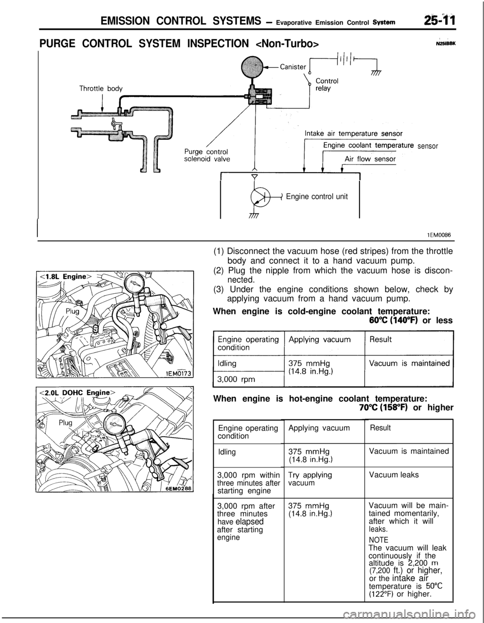
PURGE CONTROL SYSTEM INSPECTION NZ5lBEK
sensor
P+
Engine control unit
IlEM0086(1) Disconnect the vacuum hose (red stripes) from the throttle
body and connect it to a hand vacuum pump.
(2) Plug the nipple from which the vacuum hose is discon-
nected.(3) Under the engine conditions shown below, check by
applying vacuum from a hand vacuum pump.
When engine is cold-engine coolant temperature:
60% (140°F) or less
Engine operating Applying vacuum
>When engine is hot-engine coolant temperature:
70°C (158°F) or higher
Engine operating
condition
Idling3,000 rpm within
three minutes afterstarting engine
3,000 rpm after
three minutes
have elapsedafter starting
engineApplying vacuum
375
mmHg(14.8 in.Hg.1
Try wpMwvacuum375
mmHg(14.8 in.Hg.1
ResultVacuum is maintained
Vacuum leaks
Vacuum will be main-
tained momentarily,
after which it will
leaks.
NOTEThe vacuum will leak
continuously if the
altitude is 2,200
m(7,200 ft.) or higher,or the intake air
temperature is
50°C(122°F) or higher.
Page 1210 of 1216
25-14EMISSION CONTROL SYSTEMS- Evaporative Emission Control System
(5) Measure the resistance between the terminals of the
solenoid valve.
Standard value: 36-44
Q [at 20°C (68OF)]_
6EM137
AIR FLOW SENSOR, ENGINE COOLANT TEMPER-
ATURE SENSOR AND INTAKE AIR TEMPERA-
TURE SENSORTo inspect these parts, refer to GROUP
14-MPI System
Components.‘.
AIR CONDITIONER SWITCHTo inspect the air conditioner switch, refer to GROUP
24’--AirConditioner Switch.
OVERFILL LIMITER (TWO-WAY VALVE)N2BlBE&To inspect the overfill limiter (two-way valve), refer to GROUP
14-Fuel Tank.
CANISTERNzslBmTo inspect the canister, refer to GROUP
14-Fuel Line and
Vapor Line.
FUEL FILLER CAP INSPECTIONNZSIBJACheck the gasket of the fuel filler cap, and, the filler cap itself,
for damage or deformation; replace the cap if necessary.
Page 1211 of 1216
EMISSION CONTROL SYSTEMS -Exhaust Gas Recirculation (EGR) System25-l 5
EXHAUST GAS RECIRCULATION (EGR) SYSTEMN2!5lC-
2,COMPONENTS LOCATION
NameSymbolEGR control solenoid valve
CEGR temperature sensor
BEGR valve
A
EGR control
solenoid valve
Page 1212 of 1216
25-l 6EMISSION CONTROL SYSTEMS -Exhaust Gas Recirculation (EOR) SWem
4B
\\
‘\
16A0803
Name1 Svmbol
EGR control solenoid valve
D
IEGR temperature sensor
Therm0 valve AI
Page 1215 of 1216

EMISSION CONTROL SYSTEMS- Exhaust Gas Recirculation (EGR) Svstem25-19
\\
7EM0043
. .
6EM0187
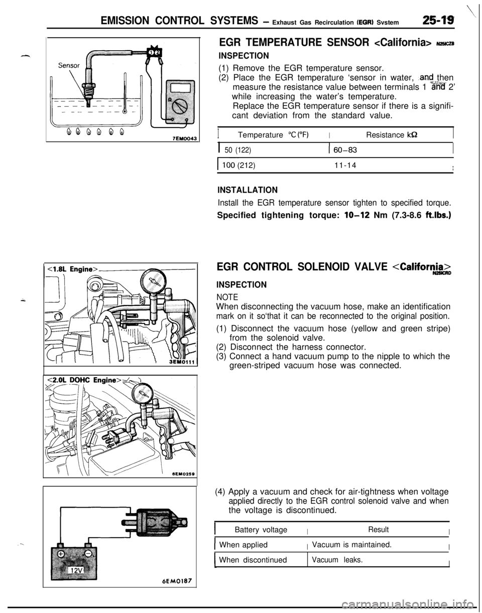
EGR TEMPERATURE SENSOR NHCZB
INSPECTION(1) Remove the EGR temperature sensor.
(2) Place the EGR temperature ‘sensor in water,
.and then
measure the resistance value between terminals 1
%%’ 2’
while increasing the water’s temperature.
Replace the EGR temperature sensor if there is a signifi-
cant deviation from the standard value.
ITemperature “C (“F)IResistance kS2I
I 50 (122)160-83I
I ~~100 (212)11-14I
INSTALLATION
Install the EGR temperature sensor tighten to specified torque.Specified tightening torque:
lo-12 Nm (7.3-8.6 ft.lbs.)
EGR CONTROL SOLENOID VALVE
INSPECTION
NOTEWhen disconnecting the vacuum hose, make an identification
mark on it so‘that it can be reconnected to the original position.(1) Disconnect the vacuum hose (yellow and green stripe)
from the solenoid valve.
(2) Disconnect the harness connector.
(3) Connect a hand vacuum pump to the nipple to which the
green-striped vacuum hose was connected.
(4) Apply a vacuum and check for air-tightness when voltage
applied directly to the EGR control solenoid valve and whenthe voltage is discontinued.
IBattery voltageIResultI
IWhen appliedIVacuum is maintained.IWhen discontinued
Vacuum leaks.I