Page 1150 of 1216
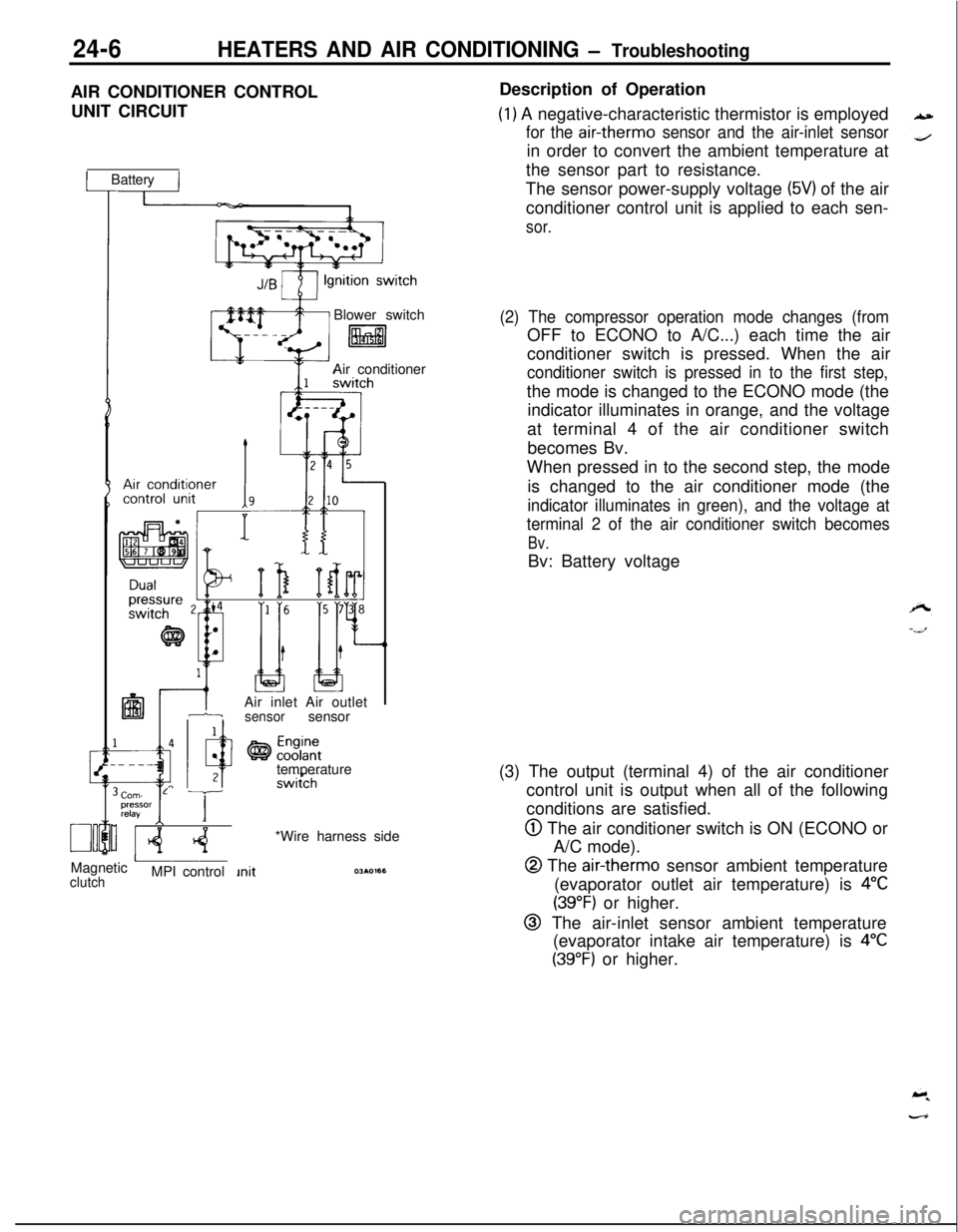
24-6HEATERS AND AIR CONDITIONING - TroubleshootingAIR CONDITIONER CONTROL
UNIT CIRCUIT
1 Battery IBlower switch
litalAir conditioner
IAir inlet Air outlet1-isensorsensor
temperature
Corn- L Tpressor
relayI IMagnetic
AclutchMPI control*Wire harness sideDescription of Operation
(1) A negative-characteristic thermistor is employed
for the air-therm0 sensor and the air-inlet sensorin order to convert the ambient temperature at
the sensor part to resistance.
The sensor power-supply voltage
(5V) of the air
conditioner control unit is applied to each sen-
sor.
(2) The compressor operation mode changes (fromOFF to ECONO to A/C...) each time the air
conditioner switch is pressed. When the air
conditioner switch is pressed in to the first step,the mode is changed to the ECONO mode (the
indicator illuminates in orange, and the voltage
at terminal 4 of the air conditioner switch
becomes Bv.
When pressed in to the second step, the mode
is changed to the air conditioner mode (the
indicator illuminates in green), and the voltage at
terminal 2 of the air conditioner switch becomes
Bv.Bv: Battery voltage
(3) The output (terminal 4) of the air conditioner
control unit is output when all of the following
conditions are satisfied.
@ The air conditioner switch is ON (ECONO or
A/C mode).
@ The air-therm0 sensor ambient temperature
(evaporator outlet air temperature) is
4°C
(39°F) or higher.
@ The air-inlet sensor ambient temperature
(evaporator intake air temperature) is
4°C
(39°F) or higher.
Page 1151 of 1216
HEATERS AND AIR CONDITIONING - Troubleshootinq
-.
’ Wire harness sideTROUBLESHOOTING HINTS
Inspection of Air Conditioner Control Unit
Disconnect the amplifier and inspect the connector on the wireharness side as shown in the chart below.
Test Conditions:
(1) Ignition switch: ON
(2) Air conditioner switch: ON
(3) Temoerature control lever: MAX COOL2OAO405
(4j Bloier switch: HI
TerminalMeasurement item
Tester connectionConditions
Specified value
1Resistancel-6-1,500f150 sz ’at 25°C (77°F)
2
10
Voltage2-3
2-8Airtcchonditioner
ContinuityContinuity3-Ground
4-Ground
Resistance5-7
-ContinuityII
8-Ground-
Voltage9-3
9-8Therm0 sensor OFF78°C (172°F)
:5k (185°F)
Voltage10-3ECONO switch
10-8
System voltageov
Continuity
Continuity1,500+
150 s-2at 25°C (77’F)
Continuity
System voltageov
System? voltageov
If the connector on the wire harness side is correct, replace the air conditioner control unit.
Page 1152 of 1216
24-8HEATERS AND AIR CONDITIONING - Troubleshooting
IARNESSES AND COMPONENTS LAYOUT DIAGRAM
1. Air conditioner switch
2. Air conditioner control unit
3. Air-inlet sensor
4.
Air-therm0 sensor
36AOO51
NameSymbolAir conditioner control unit
DAir conditioner switch
GAir inlet sensor
FAir
therm0 sensorFBlower motor High relay
E
IrrIor:enser fan motor High-Low selecting
C
NameCondenser fan motor relay
Dual pressure switch
Engine coolant temperature switch
<2.0L DOHC Engine>
Heater relay
Magnetic clutch relay
Symbol
C
BA
H
C
NOTEThe “Name” column is arranged in alphabetical order.
q \
q ---
Page 1157 of 1216
HEATERS AND AIR CONDITIONING - Service Adjustment Procedures 249*I3
--Air-therm0
sensor
Air inlet
sensor
E>aporator(3)
Set the gauge manifold in place and check whether or not
the pressure at the high-pressure side has become the
dual-pressure switch activation pressure.
(4) Replace the switch if, under ordinary conditions, there is no
continuity.Caution
The condition can be considered to be satisfactory if
there is continuity.
Never increase the pressure in a deliberate attempt to
obtain an abnormally high temperature, because to do
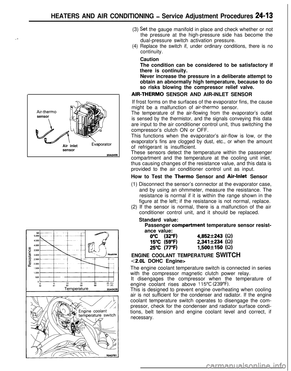
so risks blowing the compressor relief valve.AIR-THERM0 SENSOR AND AIR-INLET SENSOR
If frost forms on the surfaces of the evaporator fins, the cause
might be a malfunction of
air-therm0 sensor.
The temperature of the air-flowing from the evaporator’s outlet
is sensed by the thermistor, and the signals conveying this dataare input to the air conditioner control unit, thus switching the
compressor’s clutch ON or OFF.
This functions when the evaporator’s air-flow is low, or the
evaporator’s fins are clogged by dust, etc., or when the amountof refrigerant is insufficient.
These sensors detect the temperature within the passenger
compartment and the temperature at the cooling unit inlet,
thus causing changes of the resistance value, and this data is
provided to the air conditioner control unit as input.
How to Test the Therm0 Sensor and Air-Inlet Sensor
(1) Disconnect the sensor’s connector at the evaporator case,
and by using an ohmmeter, measure the resistance. The
resistance is normal if it is within the range shown in the
figure at the left; if the resistance is not normal, replace.
(2) If the sensor is normal, there is a malfunction of the air
conditioner control unit, and it should be replaced.
Standard value:
Passenger compartment temperature sensor resist-
ance value:
0°C (32°F)4,852+243 (S-2)
15°C (59°F)2,341+234 (S-2)
25°C (77°F)1,500+150 (52)
ENGINE COOLANT TEMPERATURE SWITCH
<2.0L DOHC Engine>
The engine coolant temperature switch is connected in series
with the compressor magnetic clutch power relay.
It disengages the compressor when the temperature of
engine coolant rises above
115°C (239°F).This is designed to prevent engine overheating when cooling
air is not sufficient for the condenser and radiator. If the enginecoolant temperature switch operates to disengage the com-
pressor, check for the condenser and radiator surface condi-
tions, belt tension and engine coolant level and correct, if
necessary.
Page 1178 of 1216
24-34HEATERS AND AIR CONDITIONING - Evaporator
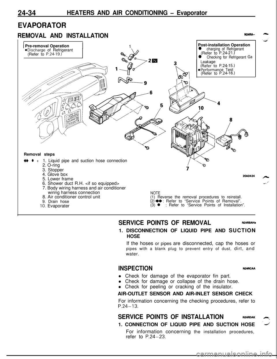
EVAPORATOR
REMOVAL AND INSTALLATION
1 Pre-removal Operation1aDischarge of Refrigerant
(Refer to P.24.19.)Post-installation Operation
l charging of Refrigerant(Refer to P.24-21.)l Checking for Refrigerant Ga:(Refer to
P.24-16.)Removal steps
N l +1. Liquid pipe and suction hose connection2. O-ring
3. Stopper
4. Glove box
5. Lower frame
6. Shower duct R.H.
7. Body wiring harness and air conditioner
wiring harness connection
8. Air conditioner control unit
9. Drain hose
10. Evaporater
2OAO424
NOTE(1) Reverse the removal procedures to reinstall.
(2) ++ : Refer to “Service Points of Removal”.
(3) l : Refer to “Service Points of Installation”.
SERVICE POINTS OF REMOVALN24RBAHa1. DISCONNECTION OF LIQUID PIPE AND SUCTION
HOSEIf the hoses or pipes are disconnected, cap the hoses or
pipes with a blank plug to prevent entry of dust, dirt, and
water.
INSPECTIONN24RCAAl Check for damage of the evaporator fin part.
l Check for damage or collapse of the drain hose.
l Check for peeling or cracking of the insulator.
AIR-OUTLET SENSOR AND AIR-INLET SENSOR CHECK
For information concerning the checking procedures, refer to
P.24-13.
SERVICE POINTS OF INSTALLATIONN24RDAK1. CONNECTION OF LIQUID PIPE AND SUCTION HOSE
For information concerning the installation procedures,
refer to
P.24-23.
Page 1179 of 1216
HEATERS AND AIR CONDITIONING - Evaporator
DISASSEMBLY AND REASSEMBLY
24-35
NURE--
3ZOAO457Disassembly steps
1. Wiring harness2. Air conditioner control unit
4*3. Clips4. Evaporater case (upper)5. Air inlet sensor
6. Air therm0 sensor
7. Evaporater case (lower)
8. Evaporater assembly9. Grommet
IO. Insulator11. Rubber insulator
12. Clip+) ++ 13. Expansion valve14. O-ringNOTE
(1) Reverse the disassembly procedures to reassyyble(2) ~~ : Refer to “Service Points of Disassembly,(3) +4 : Refer to“Service Points of Reassembly
(4) m : Non-reusable parts.
.
Page 1189 of 1216
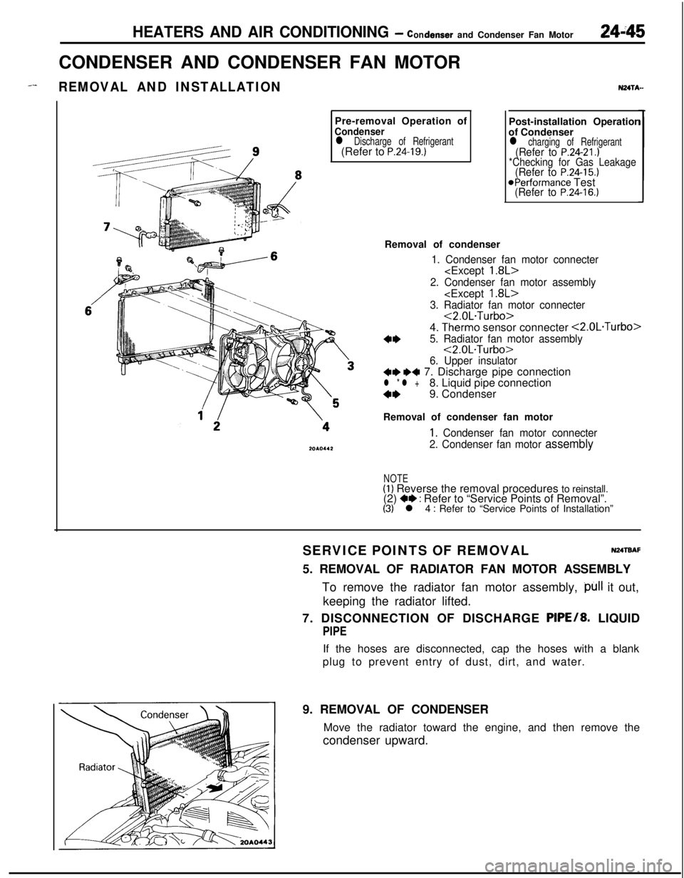
HEATERS AND AIR CONDITIONING - condenser and Condenser Fan Motor24i45CONDENSER AND CONDENSER FAN MOTOR
_--REMOVAL AND INSTALLATIONPre-removal Operation of
Condenserl Discharge of Refrigerant(Refer to P.24-19.)
NZITA-Post-installation Operatior
of Condenser
l charging of Refrigerant(Refer to P.24-21.)*Checking for Gas Leakage(Refer to P.24-15.)@Performance Test(Refer to P.24-16.)Removal of condenser
1. Condenser fan motor connecter
2. Condenser fan motor assembly
3. Radiator fan motor connecter<2.0L.Turbo>
4.
Therm0 sensor connecter <2.0L.Turbo>
4*5. Radiator fan motor assembly<2.0L.Turbo>
6. Upper insulator+e ~~ 7. Discharge pipe connectionl * l +8. Liquid pipe connection
4*9. Condenser
Removal of condenser fan motor
1, Condenser fan motor connecter
2. Condenser fan motor
assembly
NOTE(1) Reverse the removal procedures to reinstall.
(2) +e : Refer to “Service Points of Removal”.(3) l 4 : Refer to “Service Points of Installation”
SERVICE POINTS OF REMOVAL
N24TBAF5. REMOVAL OF RADIATOR FAN MOTOR ASSEMBLY
To remove the radiator fan motor assembly,
)~ll it out,
keeping the radiator lifted.
7. DISCONNECTION OF DISCHARGE PIPE/8. LIQUID
PIPEIf the hoses are disconnected, cap the hoses with a blank
plug to prevent entry of dust, dirt, and water.
9. REMOVAL OF CONDENSER
Move the radiator toward the engine, and then remove the
condenser upward.
Page 1197 of 1216
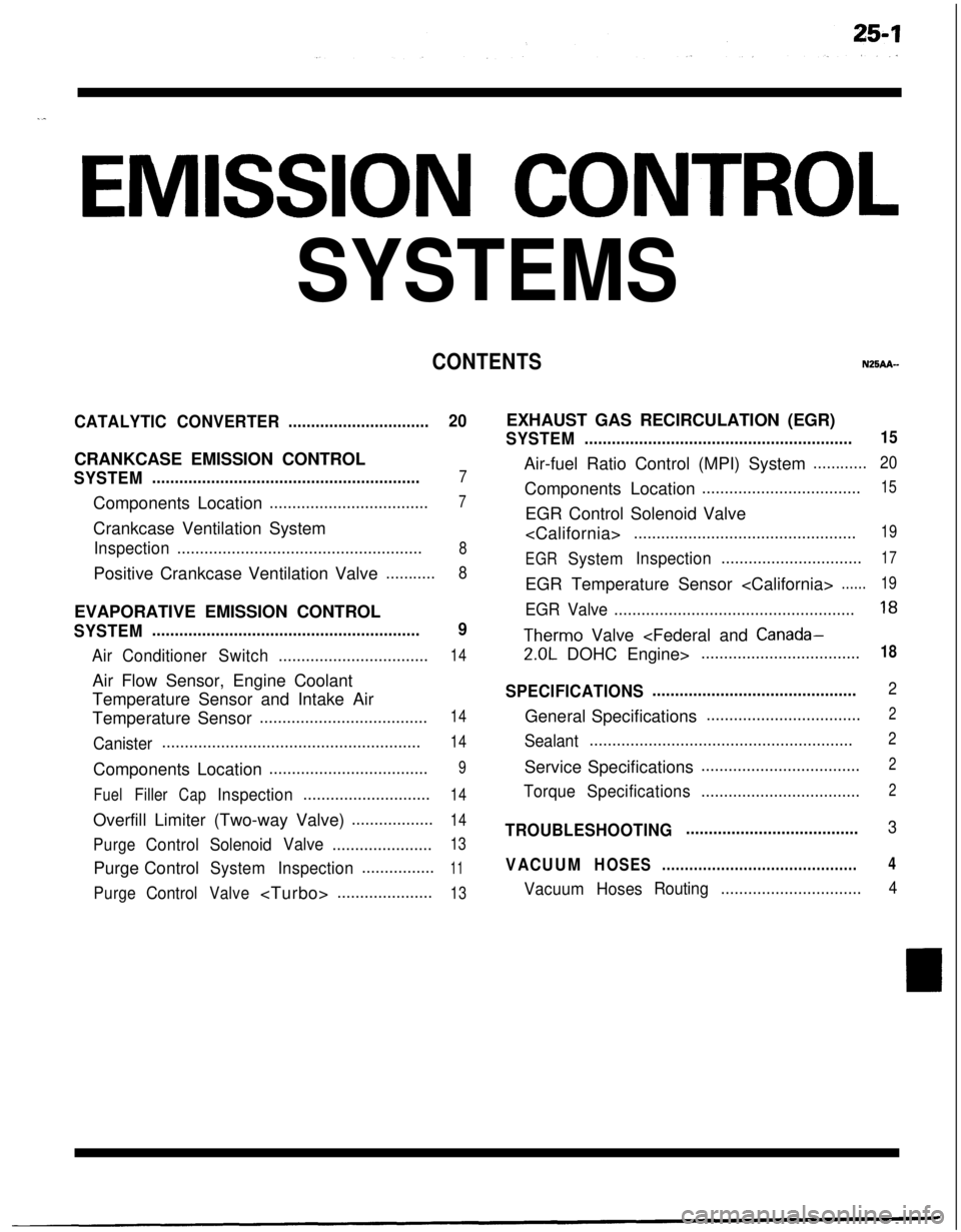
.^
EMISSION CONTROL
SYSTEMS
CONTENTSN25AA-
CATALYTICCONVERTER...............................20CRANKCASE EMISSION CONTROL
SYSTEM...........................................................7Components Location
...................................7Crankcase Ventilation System
Inspection......................................................8Positive Crankcase Ventilation Valve
...........8EVAPORATIVE EMISSION CONTROL
SYSTEM...........................................................9
AirConditionerSwitch.................................14Air Flow Sensor, Engine Coolant
Temperature Sensor and Intake Air
Temperature Sensor
.....................................14
Canister.........................................................14Components Location
...................................9
FuelFillerCapInspection............................14Overfill Limiter (Two-way Valve)
..................14
PurgeControlSolenoidValve......................13Purge Control
SystemInspection................11
PurgeControlValve.....................13EXHAUST GAS RECIRCULATION (EGR)
SYSTEM...........................................................15Air-fuel Ratio Control (MPI) System
............20Components Location
...................................15EGR Control Solenoid Valve
.................................................19
EGR
SystemInspection...............................17EGR Temperature Sensor
......19
EGR Valve.....................................................18
Therm0 Valve
2.0L DOHC Engine>...................................18
SPECIFICATIONS.............................................2General Specifications
..................................2
Sealant..........................................................2Service Specifications
...................................2
TorqueSpecifications...................................2
TROUBLESHOOTING......................................3
VACUUMHOSES...........................................4
VacuumHosesRouting...............................4