Page 953 of 1216

AUTOMATIC TRANSAXLE - Transaxle Assembly 21-259
TRANSAXLE ASSEMBLY
- REMOVAL AND INSTALLATION N2ll.kB
Pre-removal OperationPost-installation Operation*Removal of Battery*Installation of Air Cleaner, Intercooler and Air Hose@Draining of Transaxle Fluid
A (Refer to GROUP II-Intercooler.)(Refer to GROUP O-Maintenance Service.)
@Removal of Air Cleaner, Intercooler and Air Hose A*Supplying of Transaxle Fluid
(Refer to GROUP O-Maintenance Service.)
(Refer to GROUP II-Intercooler.)*Installation of Battery20-27 Nm
15-19
ft.lbs.
/ IO-14 Nm
43-55 Nm31-40
ft.lbs.
lo-12 Nm
7-9 f?.lbs.
___.Ibs.
lo-12 Nm-7-9 fi.lbs.27-34 Nm20-25
ft.lbs.30-35 Nm
22-25
ft.lbs.
09A0175
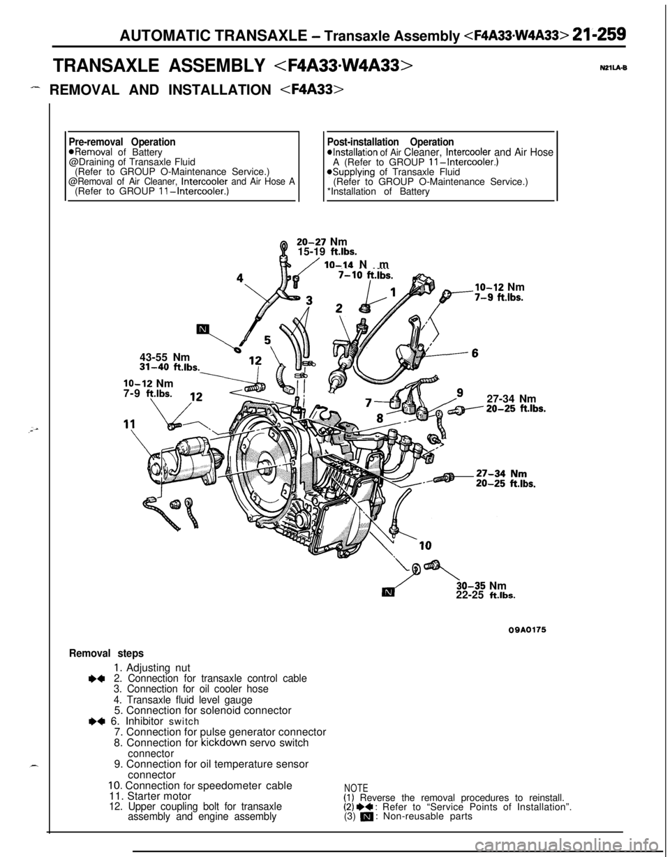
Removal steps
1. Adjusting nut+42. Connection for transaxle control cable
3. Connection for oil cooler hose
4. Transaxle fluid level gauge5. Connection for solenoid connector
e+ 6. Inhibitor switch
7. Connection for pulse generator connector
8. Connection for kickdown servo switch
connector9. Connection for oil temperature sensor
connector
10. Connection for speedometer cable
11. Starter motor
12. Upper coupling bolt for transaxle
assembly and engine assembly
NOTE(1) Reverse the removal procedures to reinstall.(2) I)+ : Refer to “Service Points of Installation”.
(3) m : Non-reusable parts
Page 955 of 1216
AUTOMATIC TRANSAXLE - Transaxle Assembly 21 kz6’1
REMOVAL AND INSTALLATION N2llA-C
(Refer to GROUP
II-Intercooler.)43-55 Nm
\i 513 \20-27 Nm
Q15-19 ft.lbs.
lo-14 NmIO-12 Nm10 ft.lbs.7-9 ftlbs.
/27-34 Nm
ft.lbs.
Y
Es.
Removal steps1. Adjusting nut
l 42. Connection for transaxle control cable3. Connection for oil cooler hose
4. Transaxle fluid level gauge5. Connection for solenoid connector
l +6. Connection for inhibitor switch connector7. Connection for pulse generator connector8. Connection for kickdown servo switch
connector9. Connection for oil temperature sensor
OQAOl63connector
10. Connection for speedometer cable11. Starter motor12. Upper coupling bolt for transaxle
assembly and engine assembly
irkeverse the removal procedures to reinstall.
(2) I)+ : Refer to “Service Points of Installation”
(3) m : Non-reusable parts
Page 960 of 1216

21-266 AUTOMATIC TRANSAXLE -Transaxle Assembly TRANSAXLE ASSEMBLY
DISASSEMBLY AND REASSEMBLY
20.Pressure pla?e21.Brake disc22.Brake plate23.Reaction plate
24. Reverse sun gear25. Thrust bearing
#826. Thrust race
#9---
1.Torque converter2.Oil pump assembly3.Gasket4.Thrust washer #I5. Front clutch assembly
6. Thrust race #37. Thrust bearing #48. Thrust washer #227. l-or-ward sun gear
9. Rear clutch assembly28. Planetary carrier assembly
10. Thrust bearing #529.Thrust bearing#I0
11. Rear clutch hub30.Output flange
12. Thrust race
#631. Oil level gauge
13. Thrust bearing #732. Oil filler tube14.Kickdownband33.
Snap ring15.Kickdowndrum34. Kickdown servo switch16.Snap ring35.Snap ring
Ii524
23
TFA0405’36.
Kickdown servo piston
37.Spring
38.Anchor rod
39.Detent assembly40. Manual control shaft
41. Parking roller support
42.Oilpan43.Gasket44. Oil temperature sensor
45.Oil screen
46. Valve body assembly
47. Manual control lever
48.Inhibitor switch49. End clutch shaft50.Bearing retainer51.Thrust bearing #I152. End clutch hub53.Thrust washer
54. End clutch assembly
55.O-ring
56. End clutch cover
57.Pulse generator58:Lock bolt59.Idler shaft60.Idlergear61.Spacer
62.Gasket
Page 962 of 1216

21-268 AUTOMATIC TRANSAXLE -Transaxle Assembly DISASSEMBLY AND REASSEMBLY
TFA0409
1.Torque converter2.Oil pump assembly3.Gasket4.Thrust washer #I5.Front clutch assembly
6. Thrust race #37.Thrust bearing #48. Thrust washer
#29.Rear clutch assembly
10. Thrust bearing #511.Rear clutch hub12.Thrust race #613.Thrust bearing #714.Kickdown band15.Kickdown drum16.Snap ring
17.Center support18.Wave spring19.Return spring20.Pressure plate21.Brake disc22.Brake plate23.Reaction plate24.Reverse sun gear25. Thrust bearing #826.Thrust race #927. Forward sun gear
28.Planetary carrier assembly29. Thrust bearing #IO30.Output flange31.Oil level gauge32.Oil filler tube33.Snap ring34.Kickdown servo switch35.
Snap ring36.
Kickdown servo piston
37.Spring38.Anchor rod39.Detent assembly40. Manual control shaft
41. Parking roller support
42.Oilpan43.Gasket44.Oil temperature sensor45.Oil screen46.Valve body assembly47.Manual control lever48.Inhibitor switch49.End clutch shaft50.Bearing retainer51.Thrust bearing #I 1
52. End clutch hub
53.Thrust washer54. End clutch assembly55.O-ring
56. End clutch cover
57.Pulse generator58.Lock bolt59.Idler shaft60.Idler gear61.Spacer
62.Gasket
Page 965 of 1216
AUTOMATIC TRANSAXLE - Transaxle Assembly 21-271
A01108. Remove the oil pan, magnet and gasket.
9. Remove the oil screen.
10. Remove the valve body mounting bolts (10).11. Remove the oil temperature sensor holder and then
remove the oil temperature sensor harness from the
clamp.12. Press the clips of the solenoid valve harness grommet,
push the grommet inside the case and remove the valve
body assembly.
13.
Pull out the oil temperature sensor.
14. Remove the parking roller support.
Page 990 of 1216
21-296 AUTOMATIC TRANSAXLE - Transaxle Assembly 76. Put the oil temperature sensor in the case.
77. Install an O-ring in the O-ring groove on top of the valve
body assembly.
78. Replace the solenoid valve harness grommet O-ring with anew O-ring.
79. Pass the solenoid valve connector through from the inside
of the transaxle case hole.
80. Insert the solenoid valve harness grommet in the case hole.,**%4
81. Temporarily install the valve body while inserting the detentplate pin in the manual valve groove. Then install the oil
temperature sensor and holder and tighten the bolts with
the specified torque.
A bolt
= 18 mm (.71 in.)
B bolt = 25 mm (.98 in.)
C bolt = 40 mm (1.57 in.)
Valve body assembly mounting bolts:
lo-12 Nm (7.5-8.5 fklbs.)
Caution
Fix the solenoid valve and oil temperature sensor
harness securely in the position shown.
82. Install the oil filter.
Oil filter mounting bolts: 5-7 Nm (4-5
ft.lbs.1
Page 1146 of 1216

24-2HEATERS AND AIR CONDITIONING - Specifications
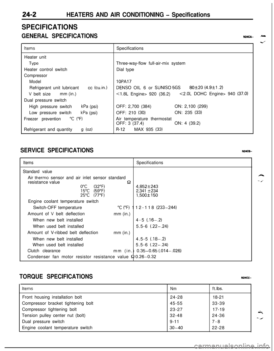
SPECIFICATIONS
GENERAL SPECIFICATIONSN24cA- -
ItemsSpecifications
Heater unit
TypeThree-way-flow full-air-mix system
Heater control switchDial type
Compressor
Model
lOPARefrigerant unit lubricantcc
(cu.in.1DENS0 OIL 6 or SUNISO 5GS80f20 (4.9&l .2)
V belt sizemm (in.)<1.8L Engine> 920 (36.2)<2.0L DOHC Engine> 940 (37.0)Dual pressure switch
High pressure switch
kPa (psi)OFF: 2,700 (384)ON: 2,100 (299)
Low pressure switch
kPa (psi)OFF: 210 (30)ON: 235 (33)
Freezer prevention“C (“F)Air temperature thermostat
OFF: 3 (37.4)ON: 4 (39.2)
Refrigerant and quantity
g bdR-12MAX 935 (33)
SERVICE SPECIFICATIONSN24CB.-
ItemsSpecifications
Standard valueAir
therm0 sensor and air inlet sensor standard
resistance value
n0°C (32°F)4,852f24315°C (59°F)2,341 f23425°C 177°F)1,500f 150Engine coolant temperature switch
Switch-OFF temperature
“C (“F) 112-118 (233-244)
Amount of
V belt deflection
mm (in.)
When new belt installed4-5
(.16-.2)When used belt installed5.5-6
(.22-.24)Amount of V-ribbed belt deflection
mm (in.)
When new belt installed4.5-5
(.18-.2)When used belt installed5.5-6
(.22-.24)
Clutch clearancemm (in.) 0.35-0.65 (.014-,026)
Condenser fan motor resistor resistance value
52 0.26-0.32
TORQUE SPECIFICATIONSN24CC-
ItemsNmft.lbs.Front housing installation bolt
24-2818-21
Compressor bracket tightening bolt
45-5533-39
Compressor tightening bolt
23-2717-19
Tension pulley center nut (bolt)
32-4824-36
Dual pressure switch
9-117-8
Engine coolant temperature switch
30-4022-28
k
- /.
Page 1149 of 1216
HEATERS AND AIR CONDITIONING - Troubleshooting24-5
From previoys page.
When the resistance of the air-
therm0 sensor is measured[with the air conditioner switch
OFF and when the ambient
temperature of the
air-therm0sensor is
25°C (77“F)], is the
measured resistance approx.
1.5f0.15 kP?
INoMalfunction of tha air-therm0Refer to P.24-6.-sensor.
Refer to P.24-6.
1Yes
When the resistance of the air-
inlet sensor is measured [with the
air conditioner switch OFF andwhen the ambient temperature of
the air-inlet sensor is 25°C (77”F)l
is the measured resistanceapprox.
1.5f0.15 k&2?I
1 Yes
Does idle-up occur immediatelyNo Malfunction of the DC motor
after the air conditioner switch is
cl800 Engine>
switched ON?Malfunction of the stepper motor
Yes~2000 DOHC Engine>
Malfunction of the MPI control unit
* Malfunction of the air conditioner
control unit.Refer to P.24-6.