Page 901 of 1216
AUTOMATIC TRANSAXLE - Troubleshooting21-207
E.L.C. 4-SPEED AUTOMATIC TRANSAXLE CONTROL COMPONENTS LAYOUT
NameSymbolNameSymbolDiagnosis connector
FPulse generator BA
Engine control unit
ISolenoid valvesCOil temperature sensor
DThrottle position sensorBPower
(PWR)/Economy (ECO) select switchGTransaxle control unitHPulse generator AAVehicle-speed sensor
E1
NOTE
1. The “Name” column is arranged in alphabetical order.2.Refer to GROUP 14-On vehicle inspection of MPI components for installation position of H throttle positionsensor.
1.8L Engine2.0L DOHCEngine
Page 907 of 1216
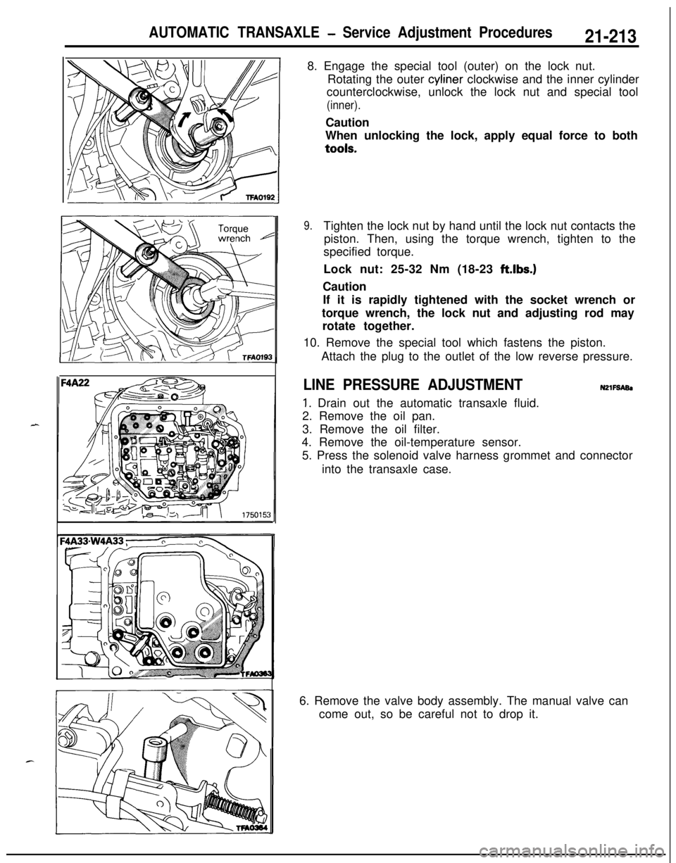
AUTOMATIC TRANSAXLE - Service Adjustment Procedures21-2138. Engage the special tool (outer) on the lock nut.
Rotating the outer cyliner clockwise and the inner cylinder
counterclockwise, unlock the lock nut and special tool
(inner).Caution
When unlocking the lock, apply equal force to bothtools.
9.Tighten the lock nut by hand until the lock nut contacts the
piston. Then, using the torque wrench, tighten to the
specified torque.
Lock nut: 25-32 Nm (18-23 ft.lbs.)
Caution
If it is rapidly tightened with the socket wrench or
torque wrench, the lock nut and adjusting rod may
rotate together.
10. Remove the special tool which fastens the piston.
Attach the plug to the outlet of the low reverse pressure.
LINE PRESSURE ADJUSTMENTN2lFSABl
1. Drain out the automatic transaxle fluid.
2. Remove the oil pan.
3. Remove the oil filter.
4. Remove the oil-temperature sensor.
5. Press the solenoid valve harness grommet and connector
into the transaxle case.
6. Remove the valve body assembly. The manual valve can
come out, so be careful not to drop it.
Page 908 of 1216
21-214AUTOMATIC TRANSAXLE - Service Adjustment Procedures
'50157
F4
1
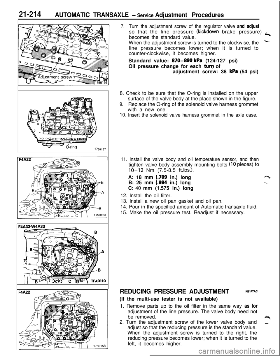
7.Turn the adjustment screw of the regulator valve and adjustso that the line pressure
(kickdown brake pressure) a,becomes the standard value.
When the adjustment screw is turned to the clockwise, the
Lline pressure becomes lower; when it is turned to
counter-clockwise, it becomes higher.
Standard value:
870-890 kPa (124-127 psi)
Oil pressure change for each turq of
adjustment screw: 38
kPa (54 psi)
8. Check to be sure that the O-ring is installed on the upper
surface of the valve body at the place shown in the figure.
9.Replace the O-ring of the solenoid valve harness grommet
with a new one.
10. Insert the solenoid valve harness grommet in the axle case.
11. Install the valve body and oil temperature sensor, and then
(IO pieces) to
tighten valve body assembly mounting bolts
IO-12 Nm (7.5-8.5 ft.lbs.).A: 18 mm
(.709 in.) long
B: 25 mm
(.984 in.) long
C: 40 mm (1.575 in.) long
12. Install the oil filter.
13. Install a new oil pan gasket and oil pan.
14. Pour in the specified amount of Automatic transaxle fluid.
15. Make the oil pressure test. Readjust if necessary.
+-t
--,,
REDUCING PRESSURE ADJUSTMENTNZlFTAC(If the multi-use tester is not available)
1. Remove parts up to the oil filter in the same way as for
adjustment of the line pressure. The valve body need not
be removed.
+%2. Turn the adjustment screw of the lower valve body and_adjust so that the reducing pressure is the standard value.
When the adjustment screw is turned to the right, the
reducing pressure becomes lower; when it is turned to the
left, it becomes higher.
Page 909 of 1216
AUTOMATIC TRANSAXLE - Service Adjustment Piocedures21-215
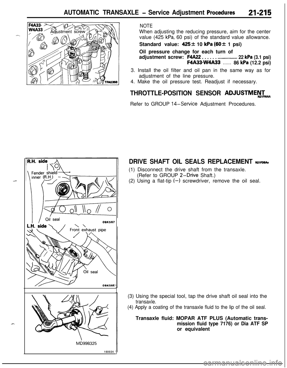
NOTEWhen adjusting the reducing pressure, aim for the center
value (425
kPa, 60 psi) of the standard value allowance.
Standard value:
425+ 10 kPa (60+ 1 psi)
Oil pressure change for each turn of
adjustment screw:
F4A22 . . . . . . ;...........,.. 22 kPa (3.1 psi)
F4A33mW4A33. . . . . .86 kPa (12.2 psi)3. Install the oil filter and oil pan in the same way as for
adjustment of the line pressure.
4. Make the oil pressure test. Readjust if necessary.
OQK567
OSKS68
Mb998325
160024
THROTTLE-POSITION SENSOR ADJUSTMEN&
Refer to GROUP
14-Service Adjustment Procedures.
DRIVE SHAFT OIL SEALS REPLACEMENT NZWWA,(1) Disconnect the drive shaft from the transaxle.
(Refer to GROUP
2-Drive Shaft.)
(2) Using a flat-tip
(-) screwdriver, remove the oil seal.
(3) Using the special tool, tap the drive shaft oil seal into the
transaxle.
(4) Apply a coating of the transaxle fluid to the lip of the oil seal.Transaxle fluid: MOPAR ATF PLUS (Automatic trans-
mission fluid type 7176) or Dia ATF SPor equivalent
Page 919 of 1216
AUTOMATIC TRANSAXLE - Transaxle Assembly 21"225
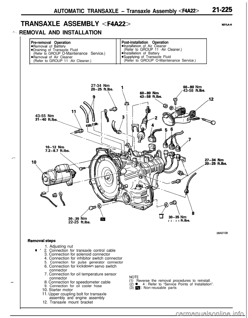
TRANSAXLE ASSEMBLY N2ll.A.A
,--. REMOVAL AND INSTALLATION
Pre-removal OperationPost-installation Operation@Removal of Battew@Installation of Air CleaneraDraining of Transaxle Fluid(Refer to GROUP 11 -Air Cleaner.)(Refer to GROUP O-Maintenance Service.)@Installation of BatteryaRemoval of Air Cleaner*Supplying of Transaxle Fluid
(Refer to GROUP 11 -Air Cleaner.)(Refer to GROUP O-Maintenance Service.)
27-34 Nm20-25
ftlbs.
1143-55 Nm31-40
ft.lbs.-\60-80
flrn60-80 Nm/43-58 ft.lbs.
//\-LTT \.30-35 Nm
AIq 30-35 Nm22-25 klbs.22-25 ft.lbs.
09A0109
Removal steps1. Adjusting nut
l *2. Connection for transaxle control cable3. Connection for solenoid connector
4. Connection for inhibitor switch connector
5. Connection for pulse generator connector
6. Connection for kickdown servo switch
connector
7. Connection for oil temperature sensor
connector
8. Connection for speedometer cable
9. Connection for oil cooler hose
10. Starter motor
11. Upper coupling bolt for transaxleassembly and engine assembly
12. Transaxle mount bracket
$?everse the removal procedures to reinstall.
(2) l 4 : Refer to “Service Points of Installation”.
(3) m : Non-reusable parts
Page 923 of 1216
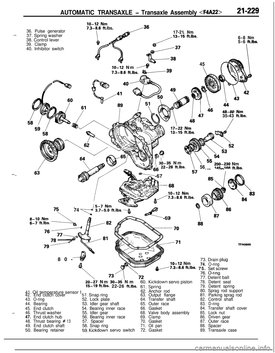
AUTOMATIC TRANSAXLE - Transaxle Assembly B-229
36. Pulse generator37. Spring washer
38. Control lever
39. Clamp40. Inhibitor switch
ln ~19 Nm
bs.17-21Nm6-8
Nm5-6ft.lbs.
-I
45
6IO-12 Nm
,----IT7.3-8.6
ftlbs.-3980-
46AR-M N~JTV -- .-.35-43 ft.iIbs.
b??io r 20-35 Nm\h\\iii-26 ft.lbs.
-,i7 ._.. .__ ._..v.-6756,,,-e30 Nmldr;-11% f-klhs.
I
,
747%!%t.lbs.3<-69
glo-12 Nm73. Drain plu!
74.O-ringv7.3-8.6 ftJbS- 75. Setscrev-^^V/8. u-nng
77. Detent ball
TFA050520-27 Nm
30-35' Nm60.Kickdown servo piston78.Detent seat15-16 ft.lbs- 22-26 ftlbs.61.Spring79.Detent spring
41. Oil temperature sensor I62. Anchor rod80. Sprag rod support42.End clutch cover51. Snap ring63.Output flange81.Parking sprag rod43.O-ring52. Lock plate64.Transfer shaft82.Control shaft44.Bearing53. Idler gear shaft65.Outer race83.D-ring
45.
End clutch54. Bearing inner race66.Gasket84.Transfer shaft cover
46.Thrust washer55. Idler gear68.Valve body assembly85.Lock nut47.End clutch hub56. Bearing inner race69.Clamp86.Driven gear48.Thrust bearing #1357. Spacer70.Gasket87.Outer race49.End clutch shaft58. Snap ring71.Oil pan88.Spacer50.Bearing retainer59. Kickdown servo switch72.Gasket89.Transaxle case
Page 925 of 1216
AUTOMATIC TRANSAXLE - Transaxle Assembly 21-237
sensor17504288. Remove the oil pan and gasket.
9. Remove the oil filter from the valve body.
10. Remove the oil-temperature sensor installation bolt; then,
after removal from the bracket, pull out from the connector
side.11. Insert the solenoid valve harness grommet and connector
into the transaxle case.
12. Remove 10 bolts and remove valve body.
13. Remove the end clutch cover mounting bolt the cover
holder, and the end clutch cover.
Page 951 of 1216
AUTOMATIC TRANSAXLE - Transaxle Assembly 21-257
7750157
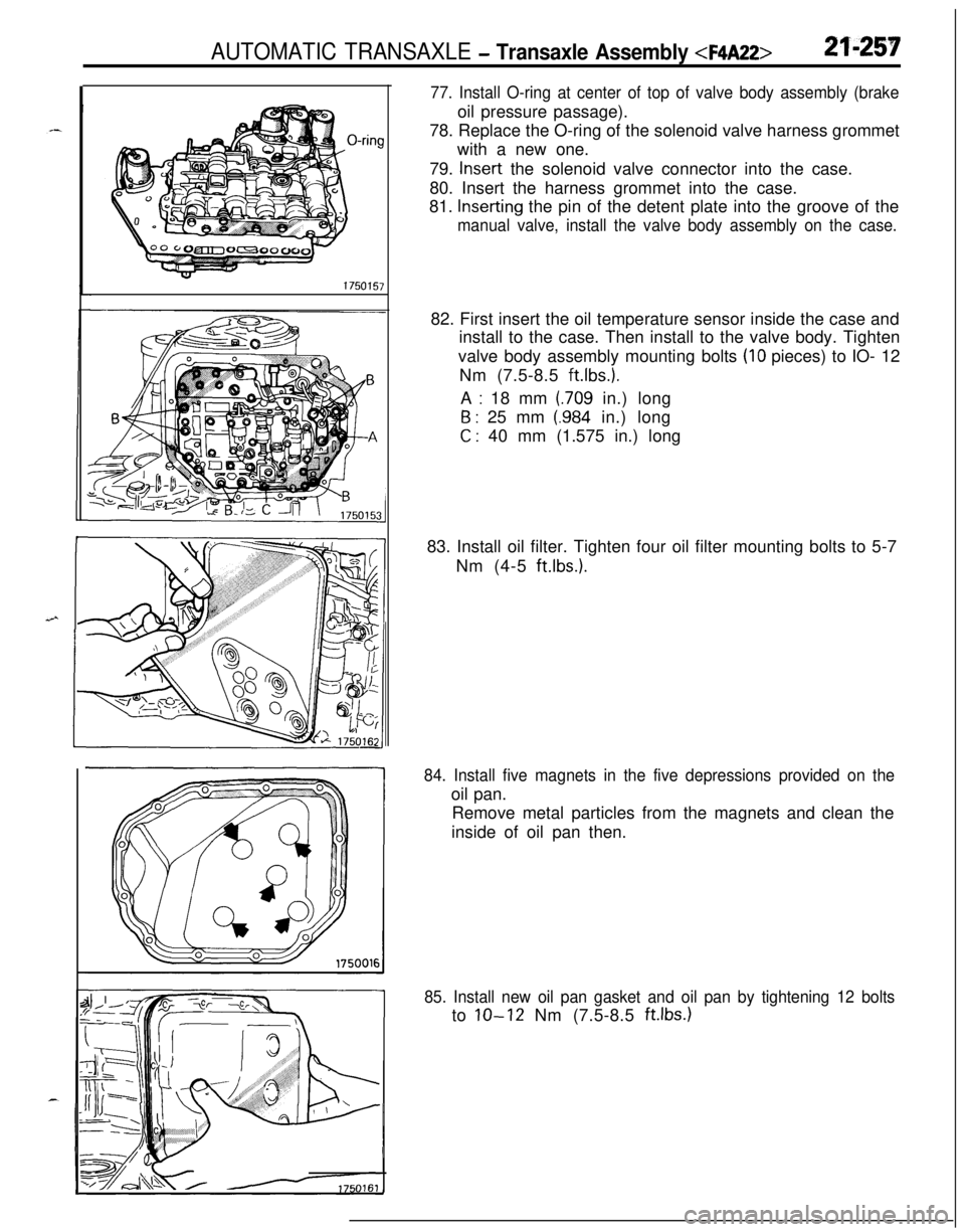
77. Install O-ring at center of top of valve body assembly (brakeoil pressure passage).
78. Replace the O-ring of the solenoid valve harness grommet
with a new one.
79.
Insert the solenoid valve connector into the case.
80. Insert the harness grommet into the case.
81.
Inserting the pin of the detent plate into the groove of the
manual valve, install the valve body assembly on the case.82. First insert the oil temperature sensor inside the case and
install to the case. Then install to the valve body. Tighten
valve body assembly mounting bolts
(IO pieces) to IO- 12
Nm (7.5-8.5
ft.lbs.).A
: 18 mm (709 in.) long
6 : 25 mm (.984 in.) long
C : 40 mm (1.575 in.) long
83. Install oil filter. Tighten four oil filter mounting bolts to 5-7
Nm (4-5
ft.lbs.1.
84. Install five magnets in the five depressions provided on theoil pan.
Remove metal particles from the magnets and clean the
inside of oil pan then.
85. Install new oil pan gasket and oil pan by tightening 12 boltsto
lo-12 Nm (7.5-8.5 ft.lbs.1