1991 MITSUBISHI ECLIPSE sensor
[x] Cancel search: sensorPage 370 of 1216

9-86ENGINE <2.0L DOHC Engine> -Camshafts and Camshaft Oil Seals
rMD998306qil seal
coatithe
mrenceof the guide.
6EN612Matingmark atMating mark at
llA0361Semi-circular packing
Awlv sealant(2) The camshaft’s dowel pins should be at the positions
shown in the figure.
17./16./15./14. INSTALLATION OF CAMSHAFT BEARING
CAPSTighten the bearing cap installation bolts to the specified
torque in two or three steps.
Caution
Tighten uniformly, otherwise the rocker arms will not
be straight.
13. INSTALLATION OF CAMSHAFT OIL SEALSUsing the special tool, press in the oil seal as shown in the
figure.
_-‘7
10. INSTALLATION OF THE CRANKSHAFT ANGLE SENSOR(1) Align the mating mark (punch mark) on the housing of
the crank angle sensor with the mating mark (notch) in
the plate.
(2) Install the crank angle sensor to the engine.
Caution
When tightening the nut of the crankshaft angle
sensor, make sure that the crank angle sensor does
not turn.(3) Check that the ignition timing is set at the standard
value. (Refer to GROUP
8-Ignition System.)
8. INSTALLATION OF SEMI-CIRCULAR PACKINGInstall the semi-circular packing to the cylinder head, and
apply a coating of the specified sealant where shown in
the figure.
Ak
Specified sealant: MOPAR Part No.4318034
or equivalent
Page 374 of 1216

9-90ENGINE <2.0L DOHC Engine> - Cylinder Head Gasket
CYLINDER HEAD GASKETNOSJA-S2.5-3.5 Nm 19
3 4 K
REIVIOVAL AND INSTALLATION2-3 ft.lbs.\ I i-6
Pre-removal Operation*Eliminating Fuel Pressure in Fuel20Line1\(Refer to GROUP 14-Service Ad-justment Procedures.)eDraining of Engine Coolant(Refer to GROUP 7-Service Adjust-
ment Procedures.)
,,vs4-6 Nm
’
II28
2936’
/w,=
3i38OlAO5.69
Removal stepsl
1. Connection for accelerator cable orthrottle cable
2. Connection for accelerator cable (Auto-
cruise control)3. Connection for oxygen sensor
temperature sensor
5. Connection for engine coolant
temperature gauge unit6. Connection for engine coolant
7. Connection for crank angle sensor
8. Connection for TPS
ISC and idle switch
10. Connection for fuel injector
12. Connection for power transistor
13. Connection for knock sensor (Turbo)
14. Connection for EGR temperature sensor
(California vehicles only)
15. Connection for ground cable
+e l + 17. Connection for radiator upper hose
/\05ADl9019. Center cover
20. Connection for spark plug cable assembly
21. Connection for air intake hose (Turbo)
22. Connection for breather hose (Turbo)
23.Airintakehose24. Connection for breather hose+e l 25. Connection for fuel high pressure hose26. O-ring
27. Connection for vacuum hoses
28. Connection for heater hose
29. Connection for water by-pass hose
30. Connection for PCV hose
31. Connection for vacuum hose (Turbo)
32. Connection for water hose (Turbo)
33. Eye-bolt (Turbo)
34. Gasket (Turbo)
35. Connection for oil pipe (Turbo)
36. Connection for vacuum hoses (Turbo)
37. Connection for fuel return hose
38. Connection for brake booster vacuum
hoseA
NOTE(1) Reverse the removal procedures to reinstall.(2) +I) : Refer to “Service Points of Removal”.
(3) ~~ : Refer to “Service Points of Installation”.
(4) m : Non-reusable parts
Page 393 of 1216

ENGINE <2.0L DOHC Engine> - Camshaft and Rocker Arm9-l 09
CAMSHAFT AND ROCKER ARMNo9LE-B
- DISASSEMBLY AND REASSEMBLY3
19-21 Nm8,14-15 ftlbs.,9 IQ&”
80-100 Nm
58-72 ftlbs.
,11IO-13 Nm7-9 ftlbs.
6EN0467
Disassembly steps
r)+ 1. Crank angle sensor+* l +2. Camshaft sprocketl +3. Bearing cap rear*4 4. Bearing cap frontl 45. Camshaft oil seall *6. Bearing cap No. 5
++ 7. Bearing cap No. 2+a 8. Bearing cap No. 4~~ 9. Beanng cap No. 3l * 1;: kz$&;;m12. Lash adjuster
13. Oil delivery body
NOTE(I) Reverse the disassembly procedures to reassemble.(2) 4e : Refer to “Service Points of Disassembly”.(3) l a : Refer to “Service Points of Reassembly”.(4) m : Non-reusable parts
SERVICE POINTS OF DISASSEMBLYNOSLBDD2. REMOVAL OF CAMSHAFT SPROCKET
(1) Using a wrench, hold the camshaft at its hexagon
(between the
No.2 and No.3 journals) and remove the
camshaft sprocket bolt.
Caution
Locking the camshaft sprocket with a tool damages
the sprocket.
(2) Remove the camshaft sprockets.
Page 394 of 1216

9-110ENGINE <2.0L DOHC Engine> - Camshaft and Rocker Arm
I
I6EN0183
I6EN0184
I
I6EN0185
,I
+Front of engine (Timing belt side)
WIB’ S’it
’ Intake side
camshaft
6E NO289Cap number
Symbolidentifying
intake or
exhaust6EN6464
I
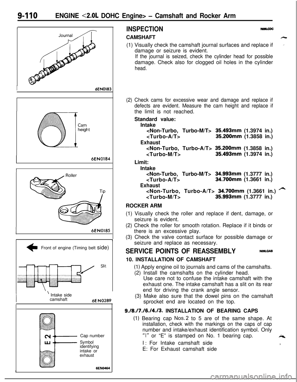
INSPECTIONCAMSHAFT
h(1) Visually check the camshaft journal surfaces and replace if
_damage or seizure is evident.
If the journal is seized, check the cylinder head for possibledamage. Check also for clogged oil holes in the cylinder
head.
(2) Check cams for excessive wear and damage and replace if
defects are evident. Measure the cam height and replace ifthe limit is not reached.
Standard value:
Intake
35493mm (1.3974 in.)
Exhaust
Limit:
Intake
Exhaust
/“4
ROCKER ARM
(1) Visually check the roller and replace if dent, damage, or
seizure is evident.
(2) Check the roller for smooth rotation. Replace if it binds or
there is an excessive play.
(3) Check the valve contact surface for possible damage or
seizure and replace as necessary.
SERVICE POINTS OF REASSEMBLYNOSLGAB10. INSTALLATION OF CAMSHAFT
(1) Apply engine oil to journals and cams of the camshafts.
(2) Install the camshafts on the cylinder head.
Use care not to confuse the intake camshaft with the
exhaust one. The intake camshaft has a slit on its rear
end for driving the crank angle sensor.
(3) Make also sure that the dowel pins on the camshaft
sprocket end are located on the top.
9./8./7./6./4./3. INSTALLATION OF BEARING CAPS
(1) Bearing cap Nos.2 to 5 are of the same shape. At
installation, check with the markings on the caps of capnumber and intake/exhaust identification symbol. Only
“I” or “E” is stamped on No. 1 bearing cap.4I
: For Intake camshaft side
E: For Exhaust camshaft side,
Page 395 of 1216

ENGINE <2.0L DOHC Engine> - Camshaft and Rocker Arm9-111_ Front of engine (Timing belt side)
0 Co@
6EN0192
MD998306Oil seal
-
Y-II6ENI01946EN030’
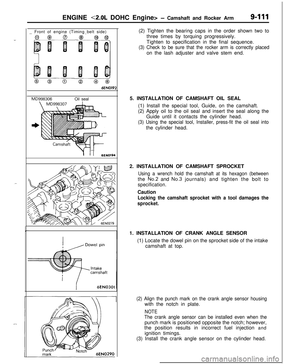
1(2) Tighten the bearing caps in the order shown two to
three times by torquing progressively.
Tighten to specification in the final sequence.
(3) Check to be sure that the rocker arm is correctly placedon the lash adjuster and valve stem end.
5. INSTALLATION OF CAMSHAFT OIL SEAL
(1) Install the special tool, Guide, on the camshaft.
(2) Apply oil to the oil seal and insert the seal along the
Guide until it contacts the cylinder head.
(3) Using the special tool, Installer, press-fit the oil seal intothe cylinder head.
2. INSTALLATION OF CAMSHAFT SPROCKET
Using a wrench hold the camshaft at its hexagon (betweenthe
No.2 and No.3 journals) and tighten the bolt to
specification.Caution
Locking the camshaft sprocket with a tool damages the
sprocket.1. INSTALLATION OF CRANK ANGLE SENSOR
(1) Locate the dowel pin on the sprocket side of the intake
camshaft at top.
(2) Align the punch mark on the crank angle sensor housingwith the notch in plate.
NOTE
The crank angle sensor can be installed even when thepunch mark is positioned opposite the notch; however,
the position results in incorrect fuel injection and
ignition timings.
(3) Install the crank angle sensor on the cylinder head.
Page 425 of 1216

--
INTAKE AND EXHAUST - SDecificationsII-3
ItemsIntake manifold
<1.8L Engine>
Accelerator cable to air intake plenum
Fuel high pressure hose to delivery pipe
Delivery pipe to intake manifold
Intake manifold stay
Engine hanger
Intake manifold to engine
Throttle body
Air intake plenum stay
Air intake plenum to intake manifold
Water outlet fitting
EGR valveEGR temperature sensor
Ground cable to air intake plenum
Control harness protector to air intake plenum
CoverIntake manifold
<2.0L DOHC Engine>
Accelerator cable to intake manifold
Throttle body stay
Fuel high pressure hose to delivery pipe
Delivery pipe to engine
Intake manifold stay
Intake manifold to engine
Mounting bolt
(M8)Mounting nut and bolt (MIO)
Ignition coil
Power transistor unit
Throttle body
EGR valveEGR temperature sensor
Control harness protector to intake manifold
Control harness clamp bolt
ixhaust manifold
<1.8L Engine>
Front exhaust pipe to exhaust manifold
Front exhaust pipe to engine
Exhaust manifold cover (A) to exhaust manifold
Exhaust manifold cover (B) to exhaust manifold
Exhaust manifold cover (A) to exhaust manifold cover (B)
Exhaust manifold to engine
Oxygen sensor
Engine oil level gauge guide mounting bolt
ixhaust manifold
<2.0L DOHC Engine (Non-Turbo)>
Front exhaust pipe to exhaust manifold
Front exhaust pipe to engine
Heat protector (A), (B)
Exhaust manifold to engine
Oxygen sensor
Engine hanger to engine
ixhaust manifold and turbocharger
<2.0L DOHC Engine (Turbo)>
Front exhaust pipe to exhaust fitting
Front exhaust pipe to engine
Heat protector (A),
(B)
Nmft.lbs.
4-6
3-4
4-6
3-4
IO-137-9
18-25
13-18
15-20II-14
15-2011-14
15-22II-16
15-2011-14
15-2011-14
17-2012-14
IO-157-11
IO-127-9
10-127-9
4-6
3-4
IO-137-9
4-6
3-4
15-22
11-16
4-6
3-4
IO-137-9
25-3018-22
15-2011-14
30-4222-30
20-2714-20
IO-127-9
15-22
11-16
15-22II-16
IO-127-9
4-6
3-4
IO-127-9
30-4022-29
30-4022-29
27-33
20-24
20-2814-20
8-106-7
15-2011-14
40-5029-36
12-15
9-l 1
30-4022-29
30-4022-29
12-15
9-l 1
25-3018-22
40-5029-36
12-15
9-l 1
40-6029-43
30-4022-29
12-15
9-11
Page 426 of 1216

11-4INTAKE AND EXHAUST- Specifications/Special Tool/Troubleshooting
ItemsEngine oil level gauge guide mounting bolt
Engine hanger to engine
Exhaust manifold to engine
Exhaust manifold to turbocharger
Oil pipe to engine
Water pipe
(B) to water inlet pipe
Waste gate actuator
Oxygen sensor
Water pipe
(B) to turbocharger
Air outlet fitting
Oil pipe to turbocharger
Water pipe (A) to turbocharger
Water pipe (A) mounting bolt
Exhaust fitting
Oil return pipe
Exhaust pipe and main muffler
Front exhaust pipe to exhaust manifold
Front exhaust pipe to exhaust fitting
Front exhaust pipe clamp
Rubber hangerFront exhaust pipe to catalytic converter
Catalytic converter to center exhaust pipe
Hanger bracket to body
Hook to center exhaust pipe
Center exhaust pipe to main muffler
Moulding to main muffler
Nmft.lbs.
12-15
9-l 112-159-11
25-3018-?255-65
40-4714-19
IO-l+
40-5029-36
IO-137-9
40-5029-36
35-5025-36
9-14
7-1028-34
20-25
35-5025-36
IO-127-9
55-65
40-47
8-106-7
30-4022-29
40-6029-43
30-4022-29
IO-157-11
40-6029-43
30-4022-29
10-157-11
10-157-11
30-4022-29
4-63-4
TROUBLESHOOTINGNllEAAB
Symptom
Exhaust gas leakage
Abnormal noiseProbable cause
Loose joints
Broken pipe or muffler
Broken separator in muffler
Broken rubber hangersInterference of pipe or muffler with vehicle body
Broken pipe or mufflerRemedy
Retighten
Repair or replace
Replace
Correct
Repair or replace
.-*
SPECIAL TOOLNllDA-
I ToolNumberNameI UseIRemoval/Installation of oxygen sensor
Removal/Installation of oxygen sensor
Fs\
Page 427 of 1216

INTAKE AND EXHAUST - Service Adjustment Procedures11-5
SERVICE ADJUSTMENT PROCEDURES
AIR CLEANER ELEMENT INSPECTION AND RE-PLACEMENTNllQBAF
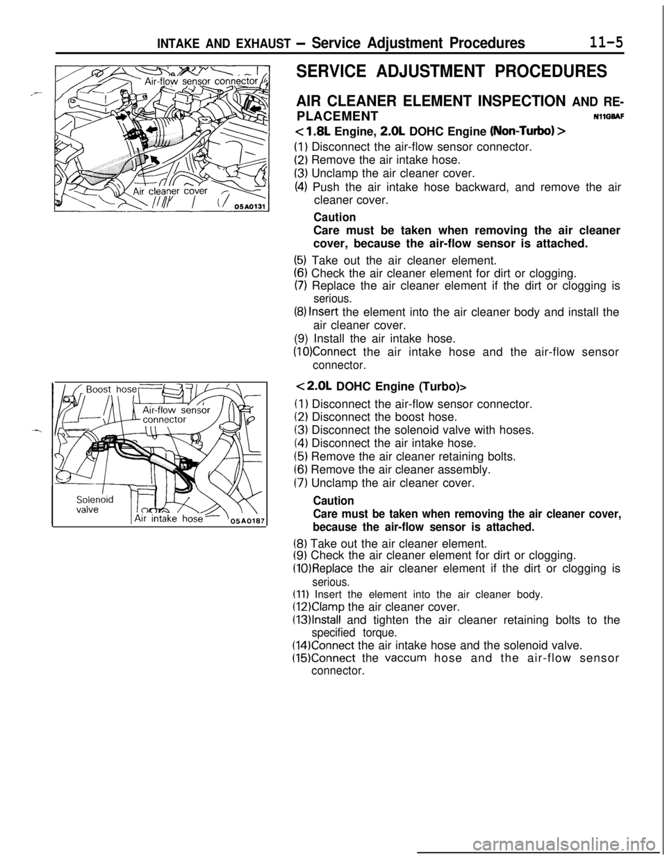
< 1.8L Engine, 2.0L DOHC Engine (Non-Turbo) >
(1) Disconnect the air-flow sensor connector.
(2) Remove the air intake hose.
(3) Unclamp the air cleaner cover.
(4) Push the air intake hose backward, and remove the air
cleaner cover.
CautionCare must be taken when removing the air cleaner
cover, because the air-flow sensor is attached.
(5) Take out the air cleaner element.
(6) Check the air cleaner element for dirt or clogging.
(7) Replace the air cleaner element if the dirt or clogging is
serious.
(8) Insert the element into the air cleaner body and install the
air cleaner cover.
(9) Install the air intake hose.
(10)Connect the air intake hose and the air-flow sensor
connector.
<2.0L DOHC Engine (Turbo)>(I
1 Disconnect the air-flow sensor connector.
(2) Disconnect the boost hose.
(3) Disconnect the solenoid valve with hoses.
(4) Disconnect the air intake hose.
(5) Remove the air cleaner retaining bolts.
(6) Remove the air cleaner assembly.
(7) Unclamp the air cleaner cover.
Caution
Care must be taken when removing the air cleaner cover,
because the air-flow sensor is attached.
(8) Take out the air cleaner element.
(9) Check the air cleaner element for dirt or clogging.
(10)Replace the air cleaner element if the dirt or clogging is
serious.
(11) Insert the element into the air cleaner body.
(12)Clamp the air cleaner cover.
(13)lnstall and tighten the air cleaner retaining bolts to the
specified torque.
(14)Connect the air intake hose and the solenoid valve.
(15)Connect the vaccum hose and the air-flow sensor
connector.