Page 429 of 1216

INTAKE AND EXHAUST - Service Adjustment ProceduresII-7
w05A0155
h61
NO06061
NO0616 I
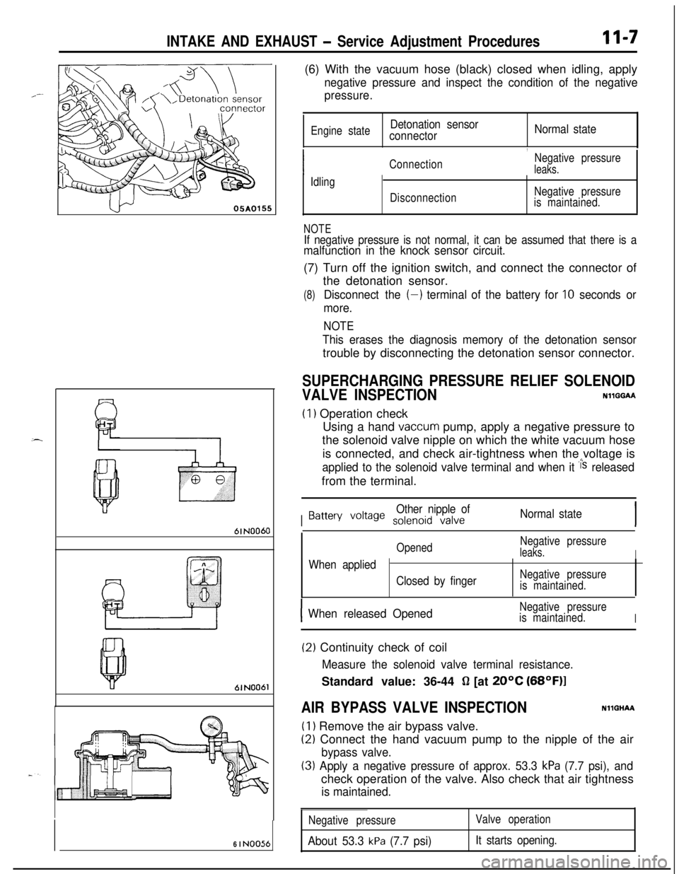
NO056(6) With the vacuum hose (black) closed when idling, apply
negative pressure and inspect the condition of the negative
pressure.
Engine stateDetonation sensor
connectorNormal state
,
ConnectionNegative pressureleaks.
Idling
DisconnectionNegative pressure
is maintained.
NOTEIf negative pressure is not normal, it can be assumed that there is amalfunction in the knock sensor circuit.(7) Turn off the ignition switch, and connect the connector of
the detonation sensor.
(8)Disconnect the (-) terminal of the battery for 10 seconds or
more.
NOTE
This erases the diagnosis memory of the detonation sensortrouble by disconnecting the detonation sensor connector.
SUPERCHARGING PRESSURE RELIEF SOLENOID
VALVE INSPECTIONNllGGAA
(1) Operation check
Using a hand
vaccum pump, apply a negative pressure to
the solenoid valve nipple on which the white vacuum hose
is connected, and check air-tightness when the voltage is
applied to the solenoid valve terminal and when it i‘s releasedfrom the terminal.
I
Other nipple ofBattery voile solenoid valveNormal state
OpenedNegative pressureleaks.IWhen applied
Closed by fingerNegative pressure
is maintained.
IWhen released OpenedNegative pressure
is maintained.
I
(2) Continuity check of coil
Measure the solenoid valve terminal resistance.Standard value: 36-44
fl [at 20°C (68OF)l
AIR BYPASS VALVE INSPECTIONNllGHAA
(1) Remove the air bypass valve.
(2) Connect the hand vacuum pump to the nipple of the air
bypass valve.
(3) Apply a negative pressure of approx. 53.3 kPa (7.7 psi), andcheck operation of the valve. Also check that air tightness
is maintained.
Negative pressure
About 53.3 kPa (7.7 psi)
Valve operation
It starts opening.
Page 430 of 1216
II-8INTAKE AND EXHAUST - Air Cleaner
AIR CLEANERREMOVAL AND INSTALLATION
< 1.8L Engine, 2.0L DOHC Engine (Non-Turbo) >
NllFA- -%
8-10 Nm
6-7 ft.1bs.y ’
LJ
*l
<2.0L DOHC Engine (Non-Turbo)>IO-13 Nm
7-9
ft.lbs.
18
9
80
05AO1374
05A0179
05A0140Removal steps1. Connection for air flow sensor
connector
2.Breather hose3. Air intake hose
4.Air cleaner
5. Air cleaner cover
6. Air cleaner element
7. Air flow sensor assembly
8. Air flow sensor gasket
9. Noise reduction filter
10.Cover11.Grommet12. Air cleaner body
13.Insulator14.Collar
15.Packing
16.Tuning pipe
17. Splash shield extension
18.Resonator
NOTE(I) Reverse the removal procedures to reinstall.(2) q : Non-reusable parts*I: <1.8L engine>*2: <2.0L DOHC engine (Non-Turbo)>
Page 431 of 1216
INTAKE AND EXHAUST - Air Cleaner
REMOVAL AND INSTALLATION
<2.0L DOHC Engine (Turbo)>
II-S
8-10 Nm6-7, ft.lbs.12-15 Nm9- 11 ftlbs.
/
8
18
05AO167
605A0182
Removal steps
1. Air pipe
B2. By-pass air hose3. Connection for air flow sensor
connector
4.Vacuum hose
5. Waste gate solenoid valve
6.Breather hose7.Purge hose8.Air cleaner9. Air intake hose
10. Air cleaner bracket11. Air cleaner cover
12. Air cleaner element13. Air flow sensor assembly
14. Air flow sensor gasket
15. Noise reduction filter
16.Cover17.Grommet
18. Air cleaner body
19.Insulator20.Collar
NOTE(1) Reverse the removal procedures to reinstall.(2) q : Non-reusable parts
Page 432 of 1216

INTAKE AND EXHAUST - Air Cleaner
< Non-Turbo >
Air flow sensorside connector
6FUO622
c Turbo >
6FUO623
INSPECTIONNllFCAB0
Check the air cleaner body, cover or packing for ~
deformation, corrosion or damage.%al
Check the air duct for damage.d0
Check the air cleaner element for clogging, contamination or
damage.
If element is slightly clogged, remove dust by blowing air
from inside of element.
AIR-FLOW SENSOR CHECK
For inspection of air-flow sensor, refer to GROUP 14-Air-Flow
Sensor Check.
INTAKE AIR TEMPERATURE SENSORN14QHABa
(1) Disconnect the air flow sensor connectors.
(2) Measure resistance between terminals @ and @
< Non-Turbo > .
(3) Measure resistance between terminals @ and @ .zJ
ITemperature”C (“F)IResistance kn
0 (32)6.020
(68)2.780
(176)0.4
(4) Measure resistance while heating the sensor using a hair
drier.
Temperature’C (OFIResistance kdl
HigherSmaller
(5) If the value deviates from the standard value or the resistance
remains unchanged, replace the air flow sensor assembly.
Page 436 of 1216
II-14INTAKE AND EXHAUST -Intake Manifold < 1.8L Engine>
/15-20 Nm
11-14
ft.lbs.
lo-13 Nm
18167-9 ft.lbs.15-20 Nm11-14
ft.lbs.I/15-20 Nm
I26IO-15 Nm7-11
ftm’bs.
-17-20 Nm
12-14 ft.lbs.15-20 Nm
Removal steps05AO180
+* l a 16. Delivery pipe, fuel injector and pressureregulator17.Insulator
18.Insulator19. Intake manifold stay20.Engine hanger
2 1.Thermostat housing22.Intake manifold23. Intake manifold gasket24. Throttle body assembly25.Gasket26. Air intake plenum stay
27. Air intake plenum
28. Air intake plenum gasket
lb+ 29. Cover 30. Gasket 31. EGR valve 32. EGR gasket
33. EGR temperature sensor 34. Water outlet fitting35. Gasket36. Thermostat
NOTE(1) Reverse the removal procedures to reinstall.
(2) a* : Refer to “Service Points of Removal”.
(3) l * : Refer to “Service Points of Installation”
(4) q : Non-reusable parts
Page 440 of 1216
11-18INTAKE AND EXHAUST - Intake Manifold < 2.0L DOHC Engine>
10-27 Nm14-20 ft.lbs.
18hIO-13 Nm
7-9
ft.lbs.15-22 Nm11-16
ft.lbs.IO-12 Nm
7-9
ftlbs.05A0197
15-22 Nm
11-16
ftlbs.
wi2” vlo-12 Nm
7-9 ftlbs.25-30 Nm
18-22
ft.lbs.
24
\‘27
28lll
Removal steps
+e l + 16. Delivery pipe, fuel injector and pressureregulator17. Insulator18. Insulator19. Intake manifold stay
20. Intake manifold21. Intake manifold gasket22. Ignition coil23. Power transistor unit24. EGR valve25. Gasket26. EGR temperature sensor 27. Air fitting 28. Gasket 05A0196
29. Connection for control harness
30. Throttle body31. Gasket
NOTE(I) Reverse the removal procedures to reinstall.(2) l * : Refer to “Service Points of Removal”.(3) l + : Refer to “Service Points of Installation”.(4) 0 : Non-reusable parts
Page 442 of 1216

II-20INTAKE AND EXHAUST - Turbocharger
TURBOCHARGER
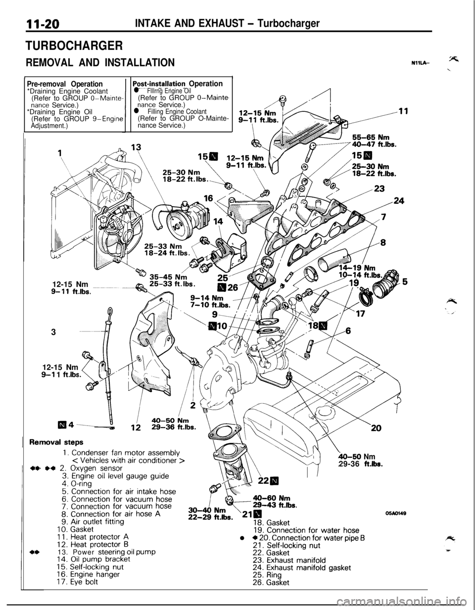
REMOVAL AND INSTALLATION
II
NHLA-
Pre-removal Operation*Draining Engine Coolant
(Refer to GROUP
0-Maintenance Service.)
*Draining Engine Oil
(Refer to GROUP g-Engine
Adjustment.)1
Po+installation Operationl Flllrng Engine Oil(Refer to GROUP O-Main@
nance Service.)l Filling Engine Coolant(Refer to GROUP O-Mainte-
nance Service.)
12-15 Nm12-15 Nm
9- 11ft.lbs.3
12-15 Nm
9-l 1 ftlbs
moval steps
1. Condenser fan motor assembly< Vehicles with air conditioner >) *4 2. Oxygen sensor3. Engine oil level gauge guide4. O-ring
5. Connection for air intake hose6. Connection for vacuum hose7. Connection for vacuum hose8. Connection for air hose A9. Air outlet fitting
10.Gasket1 1.Heat protector A12. Heat protector B13. Power steering oil pump14. Oil pump bracket15.Self-locking nut16.Engine hanger17.Eye bolt
h-50 Nm29-36 ft.lbs.
19. Connection for water hosel * 20. Connection for water pipe f321. Self-locking nut22. Gasket23. Exhaust manifold24. Exhaust manifold gasket25. Ring26. Gasket
05M1149
Page 443 of 1216
INTAKE AND EXHAUST - Turbocharger11-21
35-50 Nm25-Qg
ft-lbs*26-34 Nm
20-25 ftlbs.
\/3655-65 Nm
4o-4: ft*lbs-
35-50 Nm25-36 ftlbs.
05A0136
NOTE(1) Reverse the removal procedures to reinstall.(2) l * : Refer to “Service Points of Removal”.(3) l + : Refer to “Service Points of Installation”.(4) q : Non-reusable parts
27. Oil return pipe28.
Gasketl * l a 29. Turbocharger30. Eye bolt
31. Gasket
32. Water pipe B33. Eye bolt
34. Gasket35. Water pipe A36. Eye bolt37. Gasketw l c 38. Oil pipe39. Exhaust fitting40. GasketMD998748
1SERVICE POINTS OF REMOVALNllL9AD
2. REMOVAL OF OXYGEN SENSORDisconnect the
connector of the oxygen sensor, and install
the special tool to the oxygen sensor.
Then, using an offset (box-end) wrench, remove the oxygen
sensor.