Page 757 of 1216
MANUAL TRANSAXLE 4WD> - Differential Assembly21-63
DIFFERENTIAL ASSEMBLYNZlMMAF.
DISASSEMBLY AND REASSEMBLYDisassembly steps
l
+ 1. Bolt2. Differential drive gear
l l a3. Taper roller bearing
+e l +4. Lock pin
M 5. Pinion shaft
l 6. Pinion
e+ 7. Washer
l + 8. Sidegear
l +9. Spacer (Select)10. Differential case
130-440 Nm94- 101 ft.lbs.
\6
NOTE(1) Reverse the disassembly procedures to reassemble.(2) ~~ : Refer to “Service Points of Disassembly”.
(3) ,+ : Refer to “Service Points of Reassembly”.
(4) p : Non-reusable parts
163025
Press
F+ Bearing
SERVICE POINTS OF DISASSEMBLY
3. REMOVAL OF TAPER ROLLER BEARING
Remove the taper roller bearing using the special tool as
illustrated.
Caution ’1. Do not reuse the bearing removed from the dif-
ferential case.
2.Replace the inner and outer races of the taper roller
bearing as a set.
Page 758 of 1216

21-64MANUAL TRANSAXLE - Differential Assembly2150020
Lock pin
Llla
Lock pinDifferen-tial case
alla-ctiol
ock pinendwith2150021
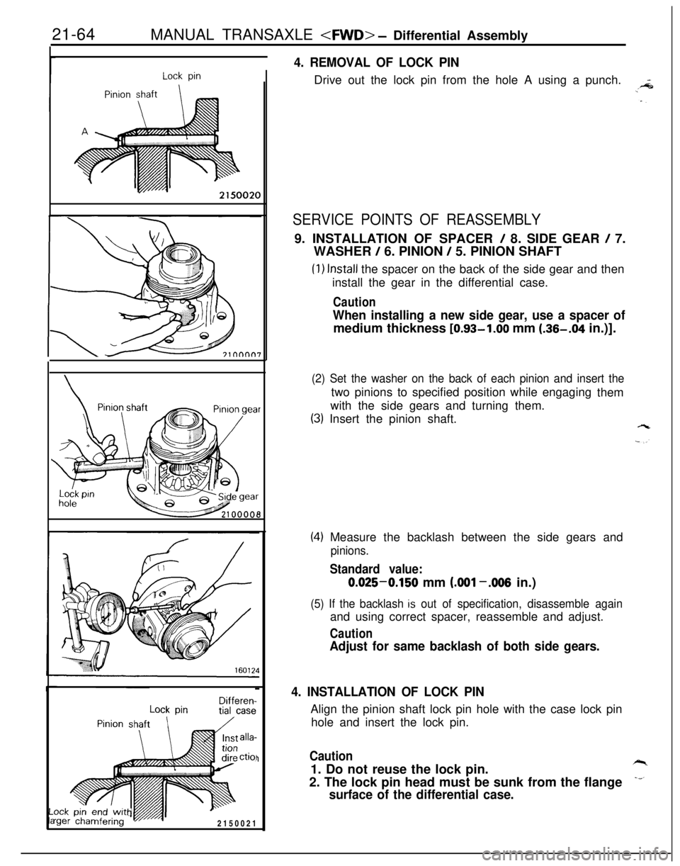
4. REMOVAL OF LOCK PINDrive out the lock pin from the hole A using a punch.
SERVICE POINTS OF REASSEMBLY9. INSTALLATION OF SPACER
/ 8. SIDE GEAR / 7.
WASHER
/ 6. PINION / 5. PINION SHAFT
(1) Install the spacer on the back of the side gear and then
install the gear in the differential case.
Caution
When installing a new side gear, use a spacer ofmedium thickness [0.93-1.00 mm (.36-.04 in.)].
(2) Set the washer on the back of each pinion and insert thetwo pinions to specified position while engaging
them
with the side gears and turning them.
(3) Insert the pinion shaft.
(4) Measure the backlash between the side gears and
pinions.
Standard value:0.025-0.150 mm
LOO1 -.006 in.)
(5) If the backlash is out of specification, disassemble againand using correct spacer, reassemble and adjust.
Caution
Adjust for same backlash of both side gears.
4. INSTALLATION OF LOCK PINAlign the pinion shaft lock pin hole with the case lock pin
hole and insert the lock pin.
Caution1. Do not reuse the lock pin.
2. The lock pin head must be sunk from the flange
surface of the differential case.
Page 759 of 1216

bierential Assembl /MANUAL TRANSAXLE - SDeedometer Gear ksemblv
, .Bearing
TFYOOIO
The numerals 0 to (8 indicate1 the tiqhtening Gequeice.210029I
SPEEDOMETER GEAR ASSEMBLY
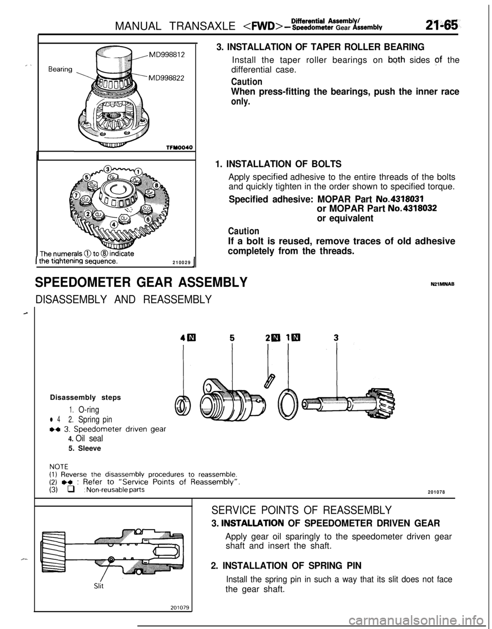
3. INSTALLATION OF TAPER ROLLER BEARINGInstall the taper roller bearings on
bqth sides of the
differential case.
Caution
When press-fitting the bearings, push the inner race
only.
1. INSTALLATION OF BOLTSApply
spec.ified adhesive to the entire threads of the bolts
and quickly tighten in the order shown to specified torque.
Specified adhesive: MOPAR Part No.4318031or MOPAR Part
No.4318032
or equivalent
CautionIf a bolt is reused, remove traces of old adhesive
completely from the threads.
DISASSEMBLY AND REASSEMBLY
NZlMNABDisassembly steps
1.O-ring
l 42.Springpin
~4 3. Speedometer driven gear
4. Oil seal5. Sleeve
NOTE(1) Reverse the disassembly procedures to reassemble.(2) ,+ : Refer to “Service Points of Reassembly”.(3) q : Non-reusable parts201078
Slit
SERVICE POINTS OF REASSEMBLY
3. INSTALLATlON OF SPEEDOMETER DRIVEN GEARApply gear oil sparingly to the speedometer driven gear
shaft and insert the shaft.
2. INSTALLATION OF SPRING PIN
Install the spring pin in such a way that its slit does not facethe gear shaft.
Page 760 of 1216
21-66MANUAL TRANSAXLE - Clutch Housing Assembly
CLUTCH HOUSING ASSEMBLYNZlMPAL
DISASSEMBLY AND REASSEMBLY
2=
-,_
1
L--15-22 Nm
11-15 ftlbs.
20-27 Nm15-19 ft.lbs.
Disassembly steps
1.Bolt2. Select lever assembly
3. Select lever shoe
4. Interlock place bolt
5.Gasket+e l *6. Lock pinj\l * l *7. Spring pin
8. Neutral return spring
9.Stopper body10.Control finger11.Interlock plate
12. Neutral return spring assembly
13.Control shaft14. Control shaft boot
l 415.Oil seal
2100019
l * 16. Needle bearing
l a 17. Needle bearing;EJ. Fil;tch housing
20: Return spring
21. Stopper plate
22. Spring pin
NOTE(1) Reverse the disassembl procedures to reassemble.(2)~~ : Refer to “Service ornts of Disassembly”.6.(3)l + : Refer to “Service Points of Reassembly”.(4) q : Non-reusable parts
Page 761 of 1216

MANUAL TRANSAXLE - Clutch Housing Assembly
SERVICE POINTS OF DISASSEMBLY
2f-67
MD998019
\
\
- Control
J$p--lever
201082
MD998\�w
-
20108:
Needle bearing’ ’
20601:
Socketwrench
I’ I20108!
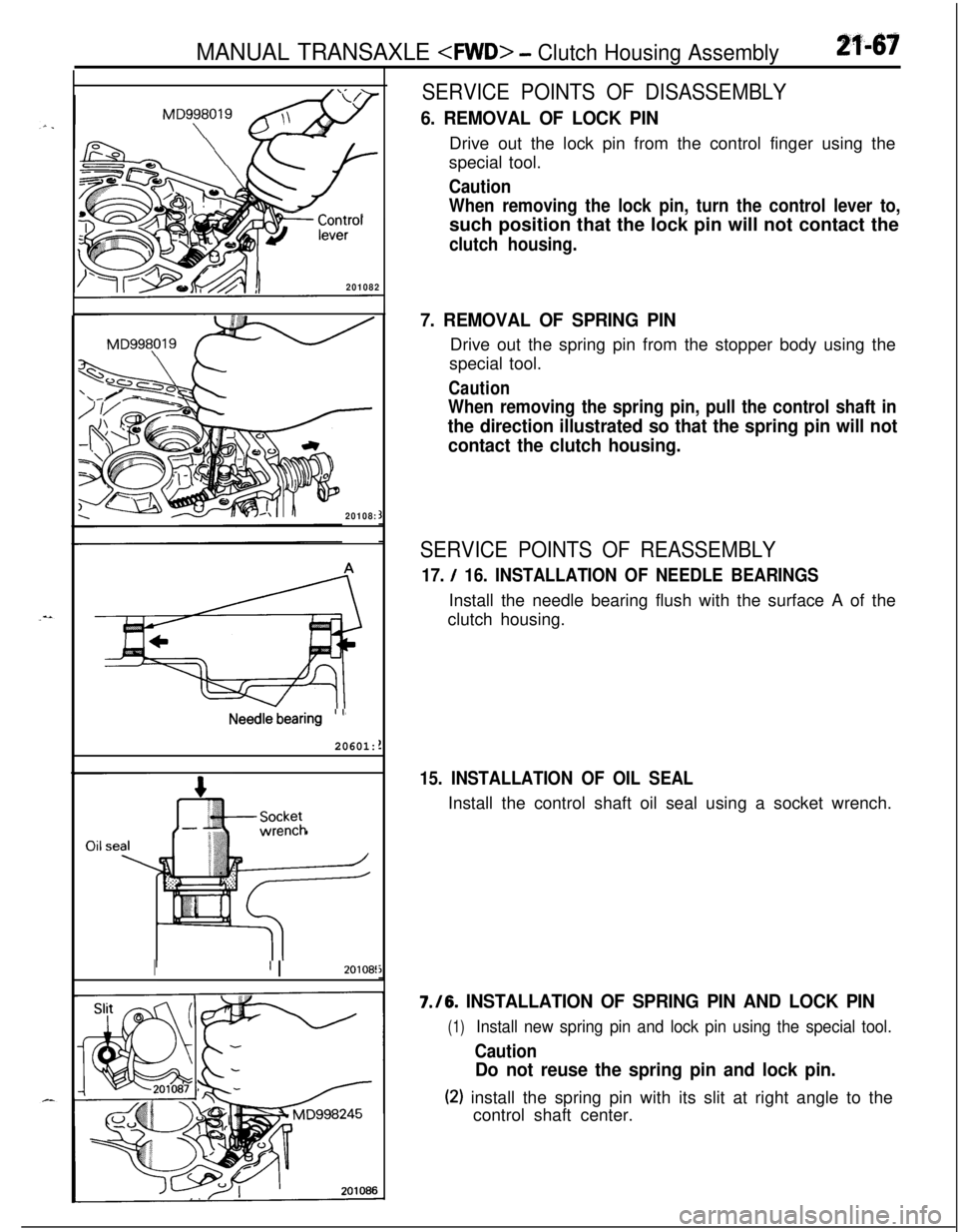
6. REMOVAL OF LOCK PINDrive out the lock pin from the control finger using the
special tool.
Caution
When removing the lock pin, turn the control lever to,such position that the lock pin will not contact the
clutch housing.
7. REMOVAL OF SPRING PINDrive out the spring pin from the stopper body using the
special tool.
Caution
When removing the spring pin, pull the control shaft in
the direction illustrated so that the spring pin will not
contact the clutch housing.
SERVICE POINTS OF REASSEMBLY
17. / 16. INSTALLATION OF NEEDLE BEARINGSInstall the needle bearing flush with the surface A of the
clutch housing.
15. INSTALLATION OF OIL SEALInstall the control shaft oil seal using a socket wrench.7./6.
INSTALLATION OF SPRING PIN AND LOCK PIN
(1)Install new spring pin and lock pin using the special tool.
Caution
Do not reuse the spring pin and lock pin.
(2) install the spring pin with its slit at right angle to the
control shaft center.
Page 763 of 1216

MANUAL TRANSAXLE 2 S~ecifCca?io’iik
2f.46g
\ ,...,
,,, .,
SPECIFICATIONS
1 L,‘S. / ,‘; ,< ’,f. : ,: ; .>r
“. . ..&
. ’ GENERAL SPECIFICATIONSNZ1.pA.B’
Items
ModelApplicable engine
TypeGear ratio
1 st
2nd
3rd
4th
5th
ReverseReduction ratio
PrimaryFront differential
TransferSpeedometer gear ratio (driven/drive)
Oil quantity
Transaxle
TransferSpecifications
(I
W5M33-2-N PZV.,A I
4G63
5-speed transaxle floor shift
3.083
I .684
1.115
0.833
0.666
3.166
1.275
3.866
1.090
29136lit.
(qts.)2.3 (2.43)
0.6
l.63)
SERVICE SPECIFICATIONSN21CB-B
d-...
Items
Standard value
TransaxleInput shaft end play
Input shaft rear bearing end play
Intermediate gear preload
Intermediate gear bearing end play
Front output shaft preload
Center differential
Viscous coupling end play
Differential case preload
Differential pinion backlash
Front differential
Differential case end play
Differential pinion backlash
TransferBevel gear set backlash
Driven bevel gear turning drive torque
Drive bevel gear shaft turning drive torqueSpecifications
o-0.05 (O-.002)
0.01-0.09 (.0004-,004)
0.08-0.14 (.0031-,006)
0.01-0.11 (.0004-,004)
0.08-0.13 (.0031-,005)
0.1-0.26 (.0039-.OlO)0.08-O. 13
LOO31 - ,005)
0.025-0.150 LOO01 -.006)
0.05-0.17 (.0020-,007)
0.025-0.150 (.OOOl-,006)
0.08-0.13 (.0031-.005)
1
.O- 1.7 Nm (0.72- 1.23 ft.lbs.11.7-2.5 Nm (1.23-1.81
ft.lbs.1
mm,.(in.)
Page 773 of 1216
MANUAL TRANSAXLE - Troubleshooting/Service Adjustment Proceduresm-79
--/OQA0024
09FOll
TROUBLESHOOTINGRefer to
P.21-12.NIlEAAE
SERVICE ADJUSTMENT
PROCED’URES
TRANSAXLE OIL LEVEL INSPECTIONN2lFBAB1Refer to GROUP O-Maintenance Service.
TRANSAXLE OIL REPLACEMENTN2lFCAH(1) Position vehicle on a flat level and remove filler and drain
plugs to drain transaxle oil.
(2) Pour in fresh transaxle oil through filler port until it reaches
the bottom of filler port.
Transaxle oil: MOPAR Hypoid gear oil or equivalent,
API classification
GL-4 or higher.
Transaxle: 2.3 liters (2.4
qts.)Transfer: 0.6 liter
(.6 qt.)
Page 774 of 1216
21-80 MANUAL TRANSAXLE -Service Adjustment Procedures
I I09K567
09K561
For L.H.For R.H.
DRIVE SHAFT OIL SEALS REPLACEMENTNZlFDAF(1) Disconnect the drive shaft from the transaxle.
(Refer to GROUP 2
- Drive Shaft.)Pas-(2) Remove the transfer assembly.
(3) Using a flat-tip
(-) screwdriver, remove the oil seal.
(4) Install the oil seals using the following procedure:
Using the special tool, tap the oil seal into the transaxle.
Note that there are two types of oil seals, one for
R.H. and
the other for L.H., and the shape of each type is different,
as shown.
-.
TRANSFER OIL SEAL REPLACEMENTN2lFGAF
(1) Pull out the propeller shaft from the transaxle. (Refer to
GROUP 16
- Propeller Shaft.)
(2) Using a flat-tip
(-) screwdriver, remove the oil seal.