Page 783 of 1216
--MANUAL TRANSAXLE
- Transaxle Assembly6?
Disassembly steps
*I) l + 54. Spring pin+I) l + 55. Spring pin+e e+ 56. Shift rail assemblyl + 57. Bolt58. Bearing retainer
+e l + 59.Intermediate gear assembly
s: W 60. Input shaft assembly
61. Outer racel 4 66. Oil seal
l 4 67. Oil seal
l + 68. Magnet
W 69. Magnet holder
70. Clutch housing assembly
NOTE
TFM0666
4*62. Outer race
63. Oil guide(1) Reverse the disassembly procedures to reassemble.(2) +I) : Refer to “Service Points of Disassembly”.4*64. Outer race
(3) ~~ : Refer to “Service Points of Reassembly”.
l 4 65. Oil seal(4) m : Non-reusable parts.
Page 784 of 1216
MANUAL TRANSAXLE - Transaxle Assembly
SERVICE POINTS OF DISASSEMBLYNZlMFAT
14. REMOVAL OF SPRING PINriiRemove the spring pin using the special tool.
.,
15.116. REMOVAL OF LOCK NUTS
(1) Unstake lock nuts of the input shaft and intermediate
gear.(2) Shift the transaxle into reverse using the control lever
and select lever.
(3) Install the special tool on the input shaft.
(4) Install the spinner handle and 10 mm
(.039 in.) bolt.
(5) Remove the lock nuts.
A
Page 786 of 1216
MANUAL TRANSAXLE - Transaxle Assembly(3) Rotate the shift controls in the direction of the arrow in
numerical order. Remove the shift lugs from the controlfinger and interlock plate.
(4) Raise each of the shift rails upward and remove them
from the clutch housing.
(5) Remove the all shift rails and forks.
59. REMOVAL OF INTERMEDIATE GEAR ASSEMBLY/
60. INPUT SHAFT ASSEMBLY
Lift up the input shaft assembly and remove the intermedi-
ate gear assembly.
61./62./64. REMOVAL OF OUTER RACE
Using the special tool, remove the outer race.
SERVICE POINTS OF REASSEMBLYN21MGAPa69. INSTALLATION OF MAGNET HOLDER/68. MAGNET
Install the magnet and magnet holder, ensuring they are
installed in the correct direction.
67. INSTALLATION OF OIL SEAL
Using the special tool, install the rear output shaft oil seal.
Page 794 of 1216
21-100MANUAL TRANSAXLE - Speedometer Gear Assembly
SPEEDOMETER GEAR ASSEMBLY
NZlMNAD
DISASSEMBLY AND REASSEMBLY
Disassembly steps
I. O-ringl *2. Spring pinl 3. Speedometer driven gear
4. Oil seal5. Sleeve
NOTE(1)Reverse the disassembly procedures to reassemble(2)**: Refer to “Service Poirits of Reassembly”.(3)q : Non-reusable parts.
SERVICE POINTS OF REASSEMBLY3. INSTALLATION OF SPEEDOMETER DRIVEN GEAR
Apply a small amount of gear oil to the speedometer drivengear shaft and insert the gear into position.
2. INSTALLATION OF SPRING PIN
lristall the spring pin so that its slit is not in contact with the
gear shaft.
Page 795 of 1216
MANUAL TRANSAXLE - 5th Speed Synchronizer Assembly2 q:-*t&f
5TH SPEED SYNCHRONIZER ASSEMBLY
/-- DISASSEMBLY AND REASSEMBLY
-Disassembly steps
1. Reverse brake ring
l 2. Synchronizer spring
3. Synchronizer sleeve
W 4. Synchronizer key
I)+ 5. Synchronizer hub
WlMHAL
. . I:,
TFMOO!56
NOTE(1)Reverse the disassembly procedures to reassemble(2)*a: Refer to “Service Points of Reassembly”.
INSPECTIONSYNCHRONIZER SLEEVE AND HUB
(1) Mate the synchronizer sleeve and hub and check to see if
they slide smoothly without binding.
(2) Make sure that the sleeve is free from damage at its inside
front and rear ends.
NOTEIf replacement is necessary, replace the synchronizer hub
and sleeve as a set.
SYNCHRONIZER KEY AND SPRING
(1) Make sure that the center protrusion of the synchronizer
key is not worn.
(2) The spring must offer proper tension with no deformation
or damage.
Page 796 of 1216
21-102MANUAL TRANSAXLE - 5th Speed Synchronizer Assembly
Oil groove
5thspeed +
$2
TFM0046
201001a,
SERVICE POINTS FOR REASSEMBLY5. INSTALLATION OF SYNCHRONIZER
tjyB.,/4. ,SYN- iic;
CHRONIZER KEY‘-a-/Install the synchronizer hub, and key in the directions as
shown.2. INSTALLATION OF SYNCHRONIZER SPRINGS
Install the synchronizer springs so that its protrusion fits
into the synchronizer key. Make sure that the protrusions inthe front and rear springs do not fit over the same key.
A
Page 797 of 1216
MANUAL TRANSAXLE - Center Differentid
CENTER DIFFERENTIAL
-4~ DISASSEMBLY AND REASSEMBLY
2210037
-
2250015
Disassembly steps
+* l +1. Taper roller bearing
l + 2. Bolt
l * l +3. Taper roller bearing
4. Output flange
I)* 5. Spacer
6. Side gear
7. Pinion shaft
8. Washer9. Pinion
10. Side gear
l + 11. Spacer
12. Center differential case
FJ)TEeverse the disassembly procedures to reassemble.(2)l *: Refer to “Service Points of Disassembly”.(3)l a: Refer to “Service Points of Reassembly”.
SERVICE POINTS OF DISASSEMBLY
1.13. REMOVAL OF TAPER ROLLER BEARINGS
Using the special tool, remove the taper roller bearings.
Caution
1. Do not reuse the bearing if it has been removed
from the shaft.
2.Replace the inner and outer races of the taper roller
bearing as a set.
Page 798 of 1216

21-104MANUAL TRANSAXLE - Center Differential
Piniongear
MD99881 2
MD998820
TFM0017
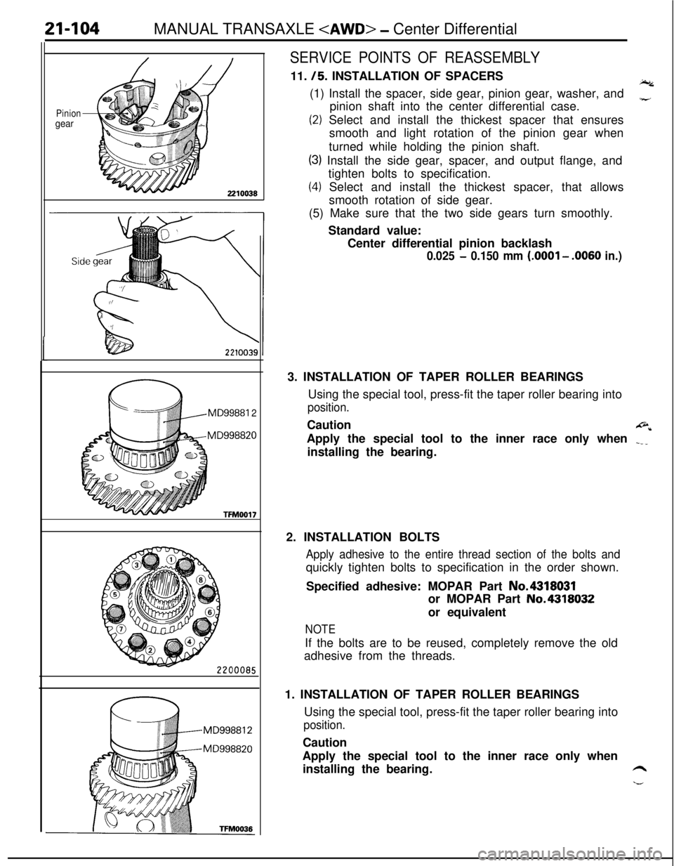
SERVICE POINTS OF REASSEMBLY11.
/5. INSTALLATION OF SPACERSI.(1) Install the spacer, side gear, pinion gear, washer, and
pinion shaft into the center differential case.
z
(2) Select and install the thickest spacer that ensures
smooth and light rotation of the pinion gear when
turned while holding the pinion shaft.
(3) Install the side gear, spacer, and output flange, and
tighten bolts to specification.
(4) Select and install the thickest spacer, that allows
smooth rotation of side gear.
(5) Make sure that the two side gears turn smoothly.
Standard value:
Center differential pinion backlash
0.025 - 0.150 mm (.OOOl - .0060 in.)3. INSTALLATION OF TAPER ROLLER BEARINGS
Using the special tool, press-fit the taper roller bearing into
position.Caution
@*Apply the special tool to the inner race only when
.___installing the bearing.
2. INSTALLATION BOLTS
Apply adhesive to the entire thread section of the bolts andquickly tighten bolts to specification in the order shown.
Specified adhesive: MOPAR Part No.4318031
or MOPAR Part No.4318032
or equivalent
NOTEIf the bolts are to be reused, completely remove the old
adhesive from the threads.
1. INSTALLATION OF TAPER ROLLER BEARINGS
Using the special tool, press-fit the taper roller bearing into
position.Caution
Apply the special tool to the inner race only when
installing the bearing.
6
h--