Page 551 of 1216
FUEL SYSTEM - Fuel Tank
FUEL TANK
i. REMOVAL AND INSTALLATION
N140A-A
_-Pre-removal Operation
eDraining of the fuel.@Release of Residual Pressure from High
Pressure Fuel Hose(Refer to
P.14-44.)Post-installation Operation
*Measurement of Fuel Pressure(Refer to P.14-44, 52.)l .Supplving of the Fuel.
1-2 Nm825-35 Nm
‘*-*: ft-‘bs*
9-14 Nm- 7-10 ft.lbs.-9
-7
03AO262
15-20 Nm
11-14 ftlbs.Removal steps
1. Fuel tankcap2. Packing
3. Drain plug4. Return hose
5. Vapor hose
4*6. High pressure fuel hose
7. Fuel filler hose
8. Cable band9. Protector
10. Vapor pipe11. Vapor hose
l 4 12. Hole cover13. Self-locking nut
14. Fuel tank
15. Overfill limiter (Two-way valve)
l + 16. Fuel pump and fuel gauge unit assembly
17. Fuel filler neck
FyTEeverse the removal procedures to reinstall.(2) ~~ : Refer to “Service Points of RemoveI”.(3) l + : Refer to “Service Points of Installation”.(4) m : Non-reusable parts
Page 552 of 1216
14-98FUEL SYSTEM -Fuel Tank 01
W636
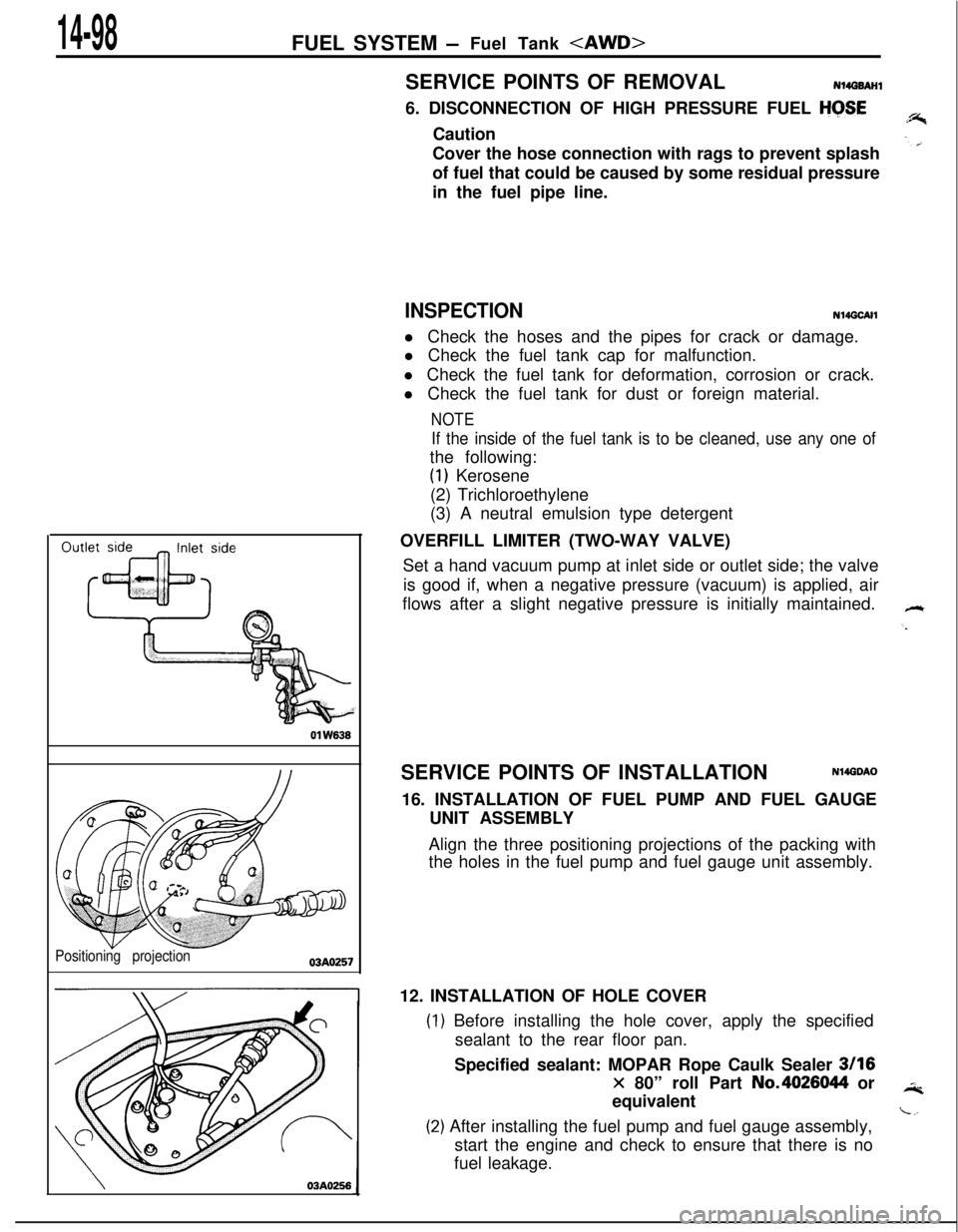
Positioning projection03AO257
\03A0256SERVICE POINTS OF REMOVAL
N14G6AHl6. DISCONNECTION OF HIGH PRESSURE FUEL
HGSECaution
Cover the hose connection with rags to prevent splash
of fuel that could be caused by some residual pressure
in the fuel pipe line.
INSPECTIONN14GCAHl Check the hoses and the pipes for crack or damage.
l Check the fuel tank cap for malfunction.
l Check the fuel tank for deformation, corrosion or crack.
l Check the fuel tank for dust or foreign material.
NOTE
If the inside of the fuel tank is to be cleaned, use any one ofthe following:
(1) Kerosene
(2) Trichloroethylene
(3) A neutral emulsion type detergent
OVERFILL LIMITER (TWO-WAY VALVE)
Set a hand vacuum pump at inlet side or outlet side; the valve
is good if, when a negative pressure (vacuum) is applied, air
flows after a slight negative pressure is initially maintained.
SERVICE POINTS OF INSTALLATION
N14GDAO16. INSTALLATION OF FUEL PUMP AND FUEL GAUGE
UNIT ASSEMBLY
Align the three positioning projections of the packing with
the holes in the fuel pump and fuel gauge unit assembly.
12. INSTALLATION OF HOLE COVER
) Before installing the hole cover, apply the specified
sealant to the rear floor pan.
Specified sealant: MOPAR Rope Caulk Sealer
3116
x 80” roll Part No.4026044 or
equivalent
!) After installing the fuel pump and fuel gauge assembly,
start the engine and check to ensure that there is no
fuel leakage.
Page 553 of 1216
FUEL SYSTEM -Fuel Pump, Fuel Gauge Unit and Overfill Limiter (Two-Way Valve) p&&g
FUEL PUMP, FUEL GAUGE UNIT AND OVERFILL LIMITER (TWO-WAY
J-.VALVE) REMOVAL AND INSTALLATION
NWJA-Pre-removal Operation
eDraining of the Fuel
Post-installation Operation
l supplying of the Fuel1.4-2.2
ft.lbs.
/ 1.4-2.2ft.lbs.
21-31 Nm
80-100 Nm+
6.5- 10ftlbs.
13AO333
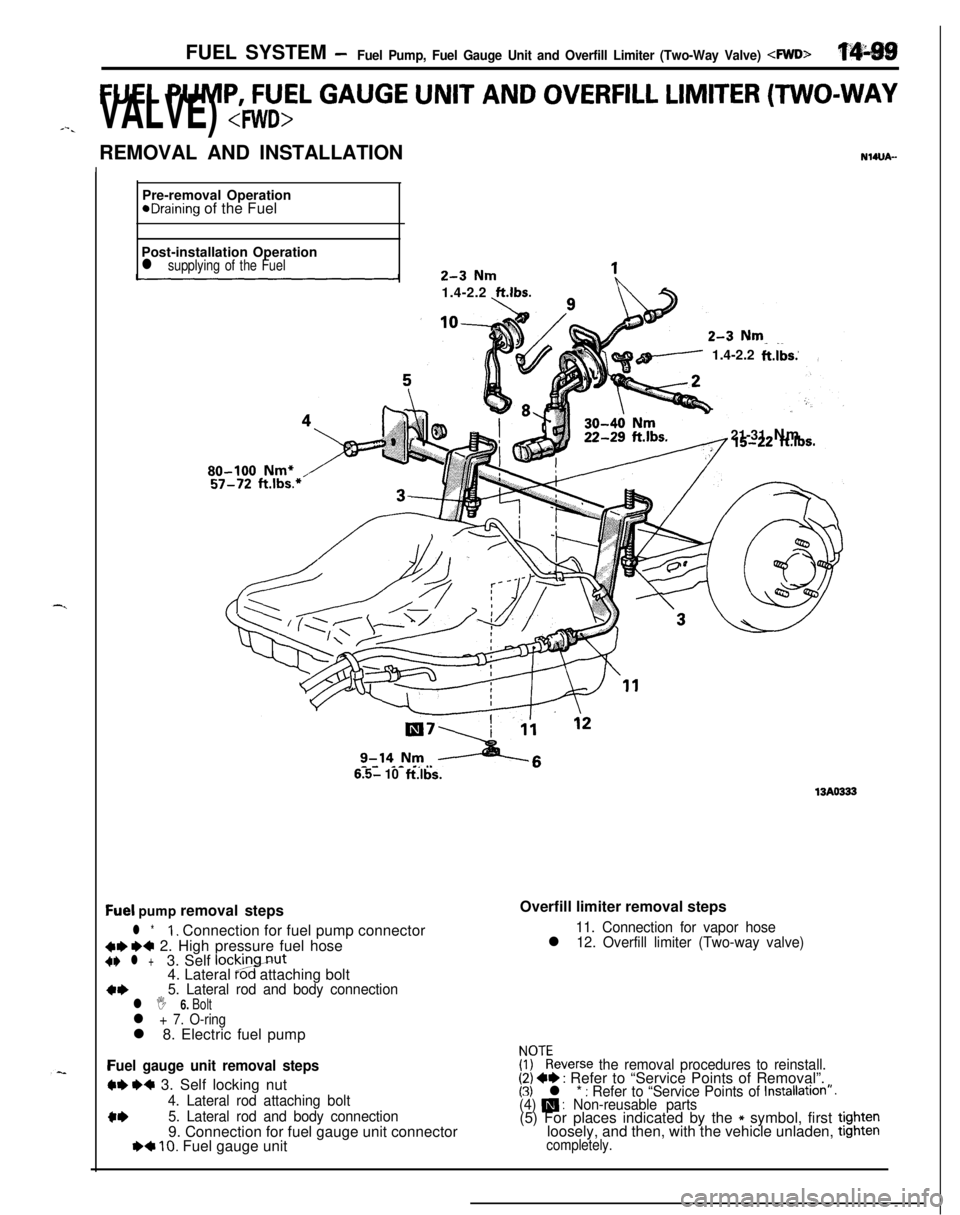
Qel pump removal steps
l *1. Connection for fuel pump connector
C+ ~~ 2. High pressure fuel hoseC+ l +3. Self lockingnut
4. Lateral Pod attaching bolt
a*5. Lateral rod and body connectionl I 6. Boltl + 7. O-ringl 8. Electric fuel pump
Fuel gauge unit removal steps
W e+ 3. Self locking nut
4. Lateral rod attaching bolt
c*5. Lateral rod and body connection9. Connection for fuel gauge unit connector
I)+ 10. Fuel gauge unitOverfill limiter removal steps
11. Connection for vapor hosel 12. Overfill limiter (Two-way valve)
FF:everse the removal procedures to reinstall.(2) +e : Refer to “Service Points of Removal”.(3) l * : Refer to “Service Points of Installation”.(4) m : Non-reusable parts(5) For places indicated by the * symbol, first tightenloosely, and then, with the vehicle unladen, tighten
completely.
Page 554 of 1216
14-100 FUEL SYSTEM- Fuel Pump, Fuel Gauge Unit and Overfill Limiter (Two-Way Valve) 4WD>SERVICE POINTS OF REMOVAL
NI4tmM2. DISCONNECTION OF HIGH PRESSURE FUEL HOSE
Refer to
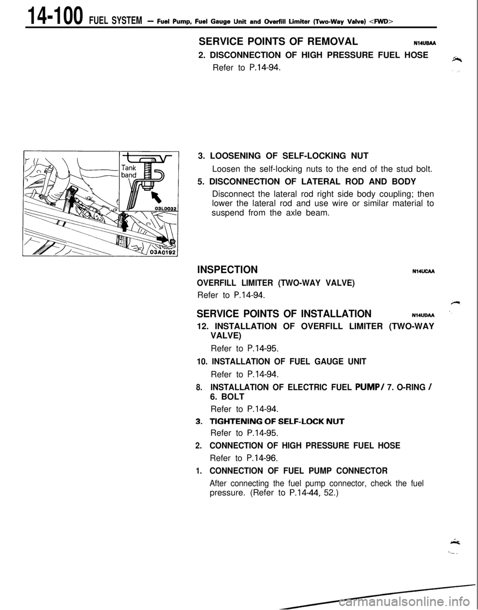
P.14-94.3. LOOSENING OF SELF-LOCKING NUT
Loosen the self-locking nuts to the end of the stud bolt.
5. DISCONNECTION OF LATERAL ROD AND BODY
Disconnect the lateral rod right side body coupling; then
lower the lateral rod and use wire or similar material to
suspend from the axle beam.
INSPECTION
OVERFILL LIMITER (TWO-WAY VALVE)Refer to
P.14-94.
N14UcM
SERVICE POINTS OF INSTALLATIONN14UDAA12. INSTALLATION OF OVERFILL LIMITER (TWO-WAY
VALVE)
Refer to
P.14-95.
10. INSTALLATION OF FUEL GAUGE UNITRefer to
P.14-94.
8.INSTALLATION OF ELECTRIC FUEL PUMP/ 7. O-RING /6. BOLT
Refer to
P.14-94.
3.TIGHTENING OF SELF-LOCK NUTRefer to
P.14-95.
2.CONNECTION OF HIGH PRESSURE FUEL HOSERefer to
P.14-96.
1.CONNECTION OF FUEL PUMP CONNECTOR
After connecting the fuel pump connector, check the fuelpressure. (Refer to P.1444, 52.)
Page 555 of 1216
FUEL SYSTEM- Fuel Pump, Fuel Gauge Unit and Overfill Limiter (Two-Way Valve)
FUEL PUMP, FUEL GAUGE UNIT AND OVERFILL LIMITER (TWO-WAY
_ VALVE) - “:“-: _...REMOVAL AND INSTALLATION
N14UA-A’
Pre-removal Operation
*Draining of the Fuel.
Post-installation Operationasupplying of the Fuel.1-2 Nm0.7-1.4 ft.lbs.
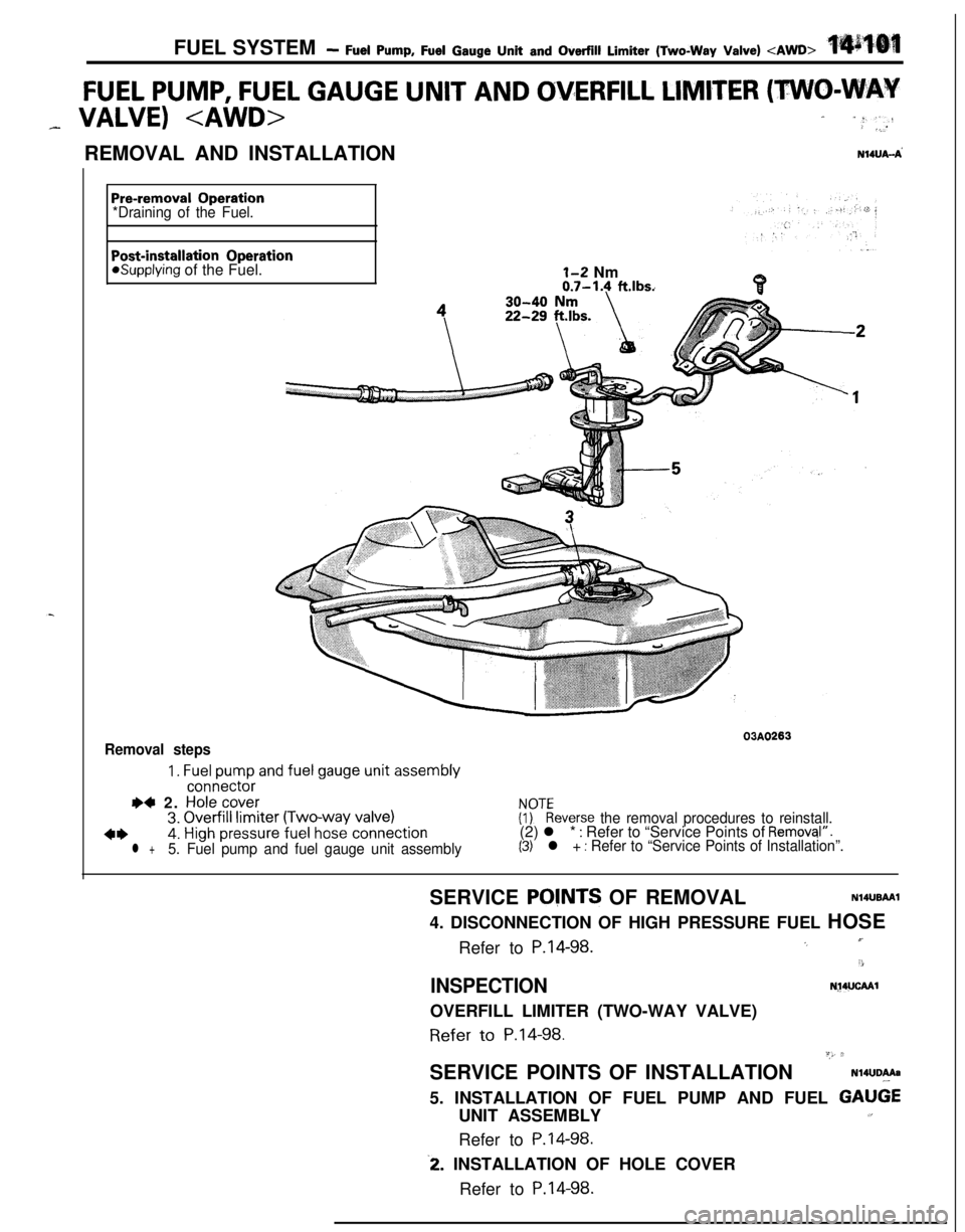
Removal steps03A0263
1. Fuel pump and fuel gauge unit assemblyconnector
I)4 2. Hole cover3. Overfill limiter (Two-way valve)FyEeverse the removal procedures to reinstall.
4*4. High pressure fuel hose connection(2) l * : Refer to “Service Points of Removql”.
l +5. Fuel pump and fuel gauge unit assembly(3) l + : Refer to “Service Points of Installation”.SERVICE
POVNTS OF REMOVALN14UBAAI4. DISCONNECTION OF HIGH PRESSURE FUEL HOSE
Refer to
P.14-98.I’.,
3
INSPECTIONN~4UCAAlOVERFILL LIMITER (TWO-WAY VALVE)Refer
to P.14-98.“,, 2SERVICE POINTS OF INSTALLATION
N14UDAAa5. INSTALLATION OF FUEL PUMP AND FUEL
GAU6EUNIT ASSEMBLY1,Refer to
P.14-98.
-2. INSTALLATION OF HOLE COVER
Refer to
P.14-98.
Page 556 of 1216
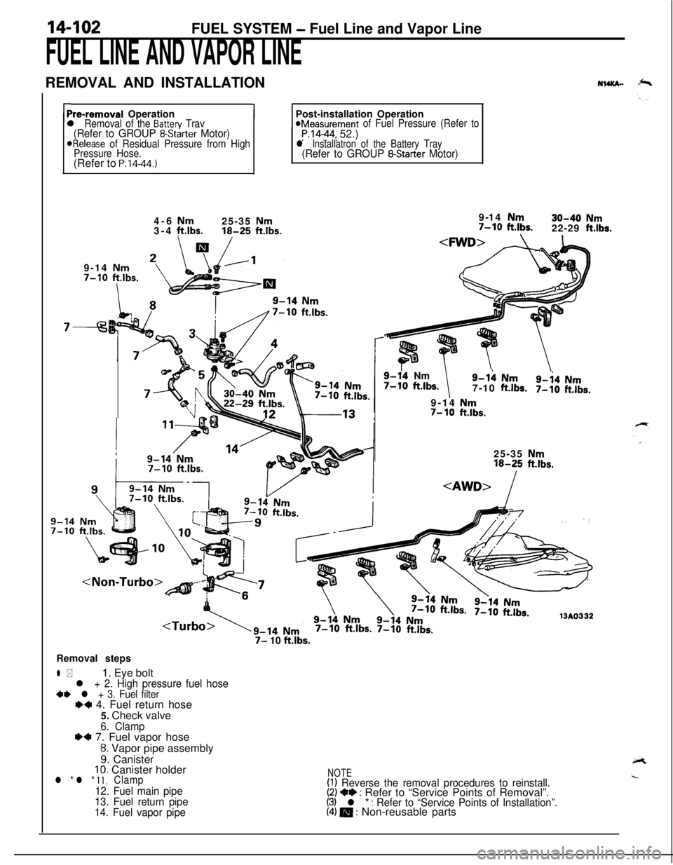
14-102FUEL SYSTEM - Fuel Line and Vapor Line
FUEL LINE AND VAPOR LINEREMOVAL AND INSTALLATION
NuKn-
rPre-removal Operationl Removal of the Batten/ Trav(Refer to GROUP 8-Starter Motor)ORelease of Residual Pressure from High
Pressure Hose.(Refer to
P.14-44.)
1Post-installation Operation*Measurement of Fuel Pressure (Refer toP.1444, 52.)l lnstallatron of the Battery Tray(Refer to GROUP 8-Starter Motor)4-6
Nm25-35 Nm3-4 ft.lbs.16-25 ftlbs.9-14 Nm7-10
ftlbs.
I
7-9-14
Nm30-40 Nm7-10 ft.lbs.22-29 ft.lbs.
9-14 Nm
7-10 ftlbs.
9-14Nm7-10 ft.lbs.9-h Nm
7-10ft.lbs.9-i4 Nm7-10ft.lbs.9-14
Nm7- 10ft.lbs.25-35
Nm16-25 ft.lbs.
7-10 ft.lbs. 7-10 ft.lbs.
7- 10 ft.lbs.Removal steps
l *1. Eye boltl + 2. High pressure fuel hose+e l + 3. Fuel filterI)+ 4. Fuel return hose
5. Check valve
6. Clamp~~ 7. Fuel vapor hose
8. Vapor pipe assembly
9. Canister
10. Canister holderl * l * 11.Clamp
12. Fuel main pipe
13. Fuel return pipe
14. Fuel vapor pipe
NOTE(I) Reverse the removal procedures to reinstall.(2) +e : Refer to “Service Points of Removal”.(3) l * : Refer to “Service Points of Installation”.(4) m : Non-reusable parts
Page 557 of 1216
-.FUEL SYSTEM
- Fuel Line pnd Vapoi- @f&
L
Mounting
bolts
pipe
03FOOO
!-03FOO7 [SERVICE. POINTS
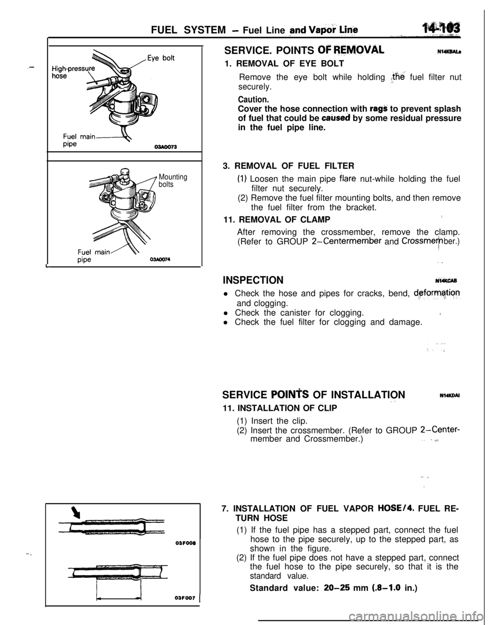
OF REMOVALN14KSAl.a1. REMOVAL OF EYE BOLT
Remove the eye bolt while holding the’ fuel filter nut
securely.
Caution.Cover the hose connection with
ragS: to prevent splash
of fuel that could be
caked by some residual pressure
in the fuel pipe line.
3. REMOVAL OF FUEL FILTER
(1) Loosen the main pipe blare nut-while holding the fuel
filter nut securely.
(2) Remove the fuel filter mounting bolts, and then remove
the fuel filter from the bracket.
11. REMOVAL OF CLAMP
!After removing the crossmember, remove the clamp.
(Refer to GROUP
2-Centermember and CrossmeTber.),.
INSPECTIONNi&CABl Check the hose and pipes for cracks, bend,
d,eforrnatiorrand clogging.
l Check the canister for clogging.
1l Check the fuel filter for clogging and damage.
SERVICE
POINTS OF INSTALLATION~aNl4KDAl11. INSTALLATION OF CLIP
(1) Insert the clip.
(2) Insert the crossmember. (Refer to GROUP
2-Center-member and Crossmember.),. ,,$l
”7. INSTALLATION OF FUEL VAPOR
HOSE/4. FUEL RE-
TURN HOSE
(1) If the fuel pipe has a stepped part, connect the fuel
hose to the pipe securely, up to the stepped part, as
shown in the figure.
(2) If the fuel pipe does not have a stepped part, connect
the fuel hose to the pipe securely, so that it is the
standard value.Standard value:
20-25 mm (.&I.0 in.)
Page 558 of 1216
FUEL SYSTEM - Fuel Line and VaDor Line/Fuel Filter
High-pressur
hose
f+-----Eye bolt
Gasket
Fuel filter
Flare nut
Fuel main
pipe
\-Apply engine
&ring Oi’
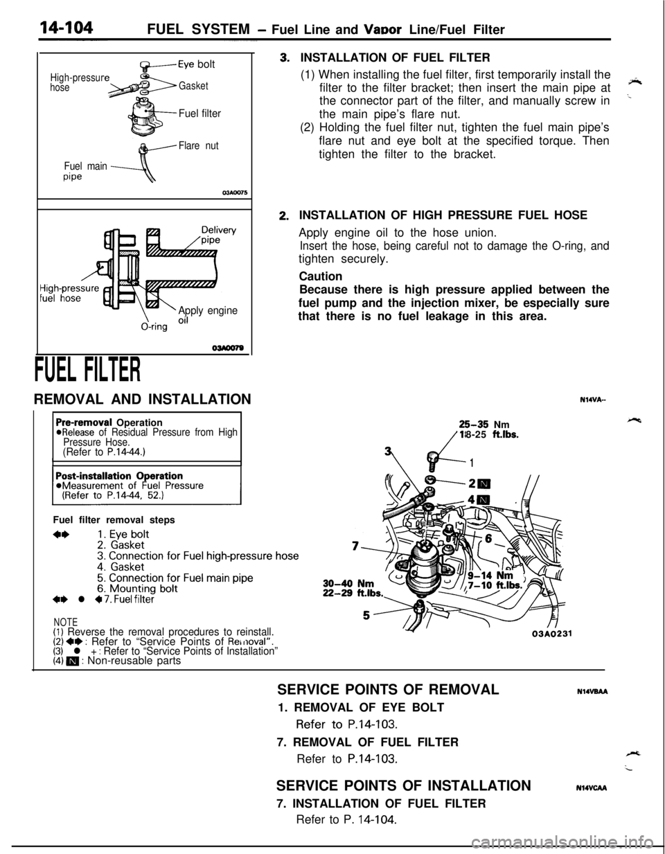
FUEL FILTERREMOVAL AND INSTALLATION3.2.INSTALLATION OF FUEL FILTER
(1) When installing the fuel filter, first temporarily install the
filter to the filter bracket; then insert the main pipe at
‘*the connector part of the filter, and manually screw in
..the main pipe’s flare nut.
(2) Holding the fuel filter nut, tighten the fuel main pipe’s
flare nut and eye bolt at the specified torque. Then
tighten the filter to the bracket.
Pre-removal Operation@Release of Residual Pressure from High
Pressure Hose.
(Refer to P.14-44.)IIFuel filter removal steps
**1. Eye bolt2. Gasket3. Connection for Fuel high-pressure hose
4. Gasket
5. Connection for Fuel main pipe6. Mounting bolt+e l 4 7. Fuel filter
NOTE(1) Reverse the removal procedures to reinstall.(2) +e : Refer to “Service Points of Removal”.(3) l + : Refer to “Service Points of Installation”(4) m : Non-reusable partsINSTALLATION OF HIGH PRESSURE FUEL HOSE
Apply engine oil to the hose union.
Insert the hose, being careful not to damage the O-ring, andtighten securely.
Caution
Because there is high pressure applied between the
fuel pump and the injection mixer, be especially sure
that there is no fuel leakage in this area.
N14VA-25-35 Nm
18-25
ft.lbs.
vd-
7’
1
Y03A0231SERVICE POINTS OF REMOVAL
NlIVBAA1. REMOVAL OF EYE BOLT
Refer to P.14-103.
7. REMOVAL OF FUEL FILTER
Refer to
P.14-103.SERVICE POINTS OF INSTALLATION
7. INSTALLATION OF FUEL FILTER
Refer to P. 14-104.
N14VCAA