Page 539 of 1216
FUEL SYSTEM - Injector/Throttle Body <1.8L Engine>14-85
Delivery pipe
Fuel pres
regulator
O-ringY pipe
O-kg
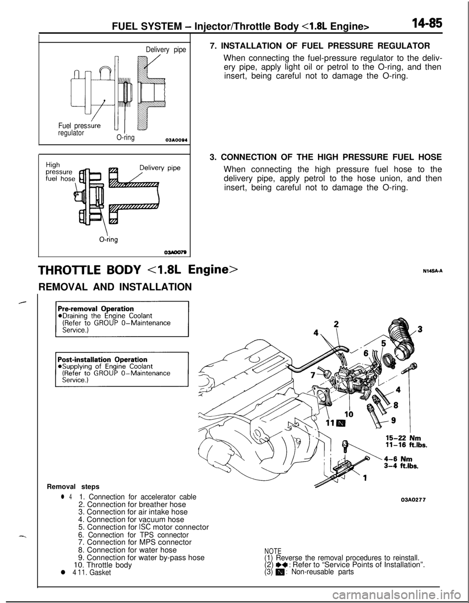
OWOO797. INSTALLATION OF FUEL PRESSURE REGULATOR
When connecting the fuel-pressure regulator to the deliv-
ery pipe, apply light oil or petrol to the O-ring, and then
insert, being careful not to damage the O-ring.
3. CONNECTION OF THE HIGH PRESSURE FUEL HOSE
When connecting the high pressure fuel hose to the
delivery pipe, apply petrol to the hose union, and then
insert, being careful not to damage the O-ring.
THROTTLE BODY 4.8L Engine>REMOVAL AND INSTALLATION
Removal steps
l 41. Connection for accelerator cable2. Connection for breather hose
3. Connection for air intake hose
4. Connection for vacuum hose
5. Connection for
ISC motor connector
6. Connection for TPS connector7. Connection for MPS connector
8. Connection for water hose
9. Connection for water by-pass hose
10. Throttle bodyl 4 11. Gasket
03AO277
NOTE(1) Reverse the removal procedures to reinstall.(2) I)+ : Refer to “Service Points of Installation”.(3) m : Non-reusable parts
Page 540 of 1216
14-86FUEL SYSTEM - Throttle Bodv 4.8L Enaine>
Air intakeplenum sideISERVICE POINTS OF INSTALLATION
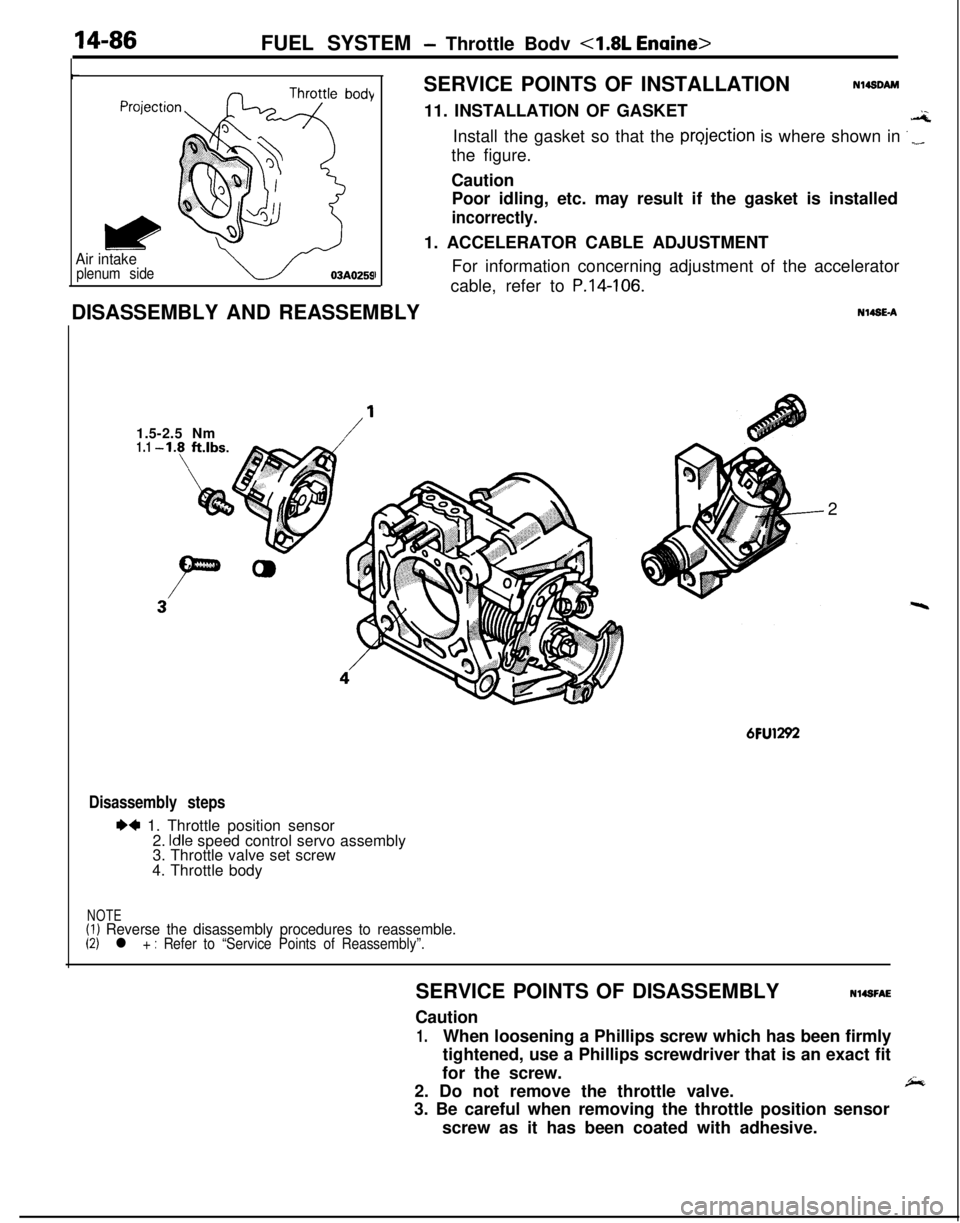
Nl4sDAM11. INSTALLATION OF GASKET
.aInstall the gasket so that the
projection is where shown in ‘_the figure.
Caution
Poor idling, etc. may result if the gasket is installed
incorrectly.1. ACCELERATOR CABLE ADJUSTMENT
For information concerning adjustment of the accelerator
cable, refer to
P.14-106.DISASSEMBLY AND REASSEMBLYN14SE-A
1.5-2.5 Nm
/’1.12
6FU1292
Disassembly steps
I)4 1. Throttle position sensor
2. Idle speed control servo assembly
3. Throttle valve set screw
4. Throttle body
NOTE(1) Reverse the disassembly procedures to reassemble.(2) l + : Refer to “Service Points of Reassembly”.SERVICE POINTS OF DISASSEMBLYN14SFAE
Caution
1.When loosening a Phillips screw which has been firmly
tightened, use a Phillips screwdriver that is an exact fit
for the screw.
2. Do not remove the throttle valve.
,&3. Be careful when removing the throttle position sensor
screw as it has been coated with adhesive.
Page 542 of 1216
14-88FUEL SYSTEM - Throttle Body 4.8L Engine>
,
Throttle position
round
sensor output
7FUO535
Motor positionsensor connector
6FU1247SERVICE POINTS OF REASSEMBLYN14SGADa
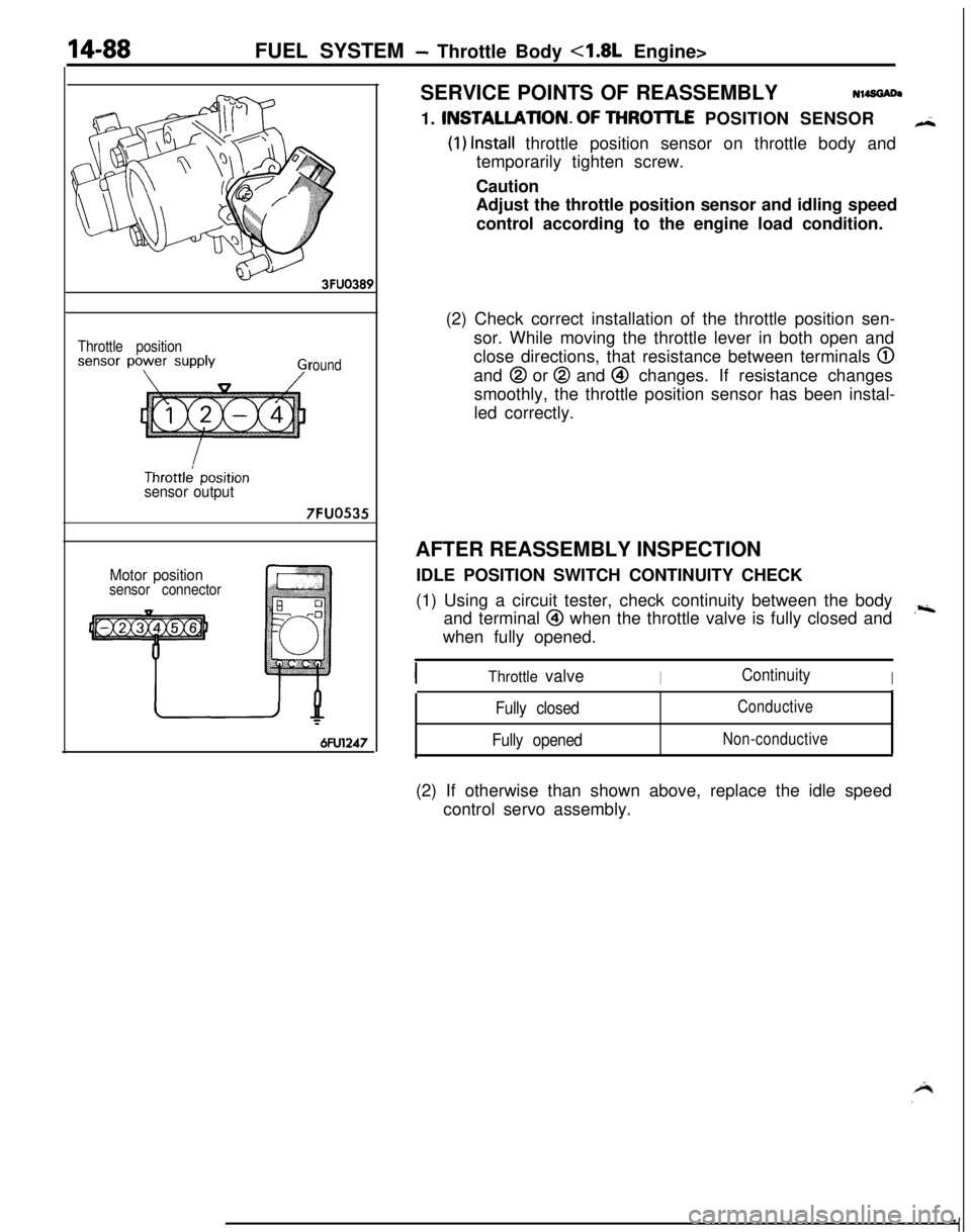
1. INSTALLATlON.OF THROlTLE POSITION SENSOR
H
(1) Install throttle position sensor on throttle body and
temporarily tighten screw.
Caution
Adjust the throttle position sensor and idling speed
control according to the engine load condition.
(2) Check correct installation of the throttle position sen-
sor. While moving the throttle lever in both open and
close directions, that resistance between terminals
@and
@ or @ and @ changes. If resistance changes
smoothly, the throttle position sensor has been instal-
led correctly.
AFTER REASSEMBLY INSPECTION
IDLE POSITION SWITCH CONTINUITY CHECK
(1) Using a circuit tester, check continuity between the body
and terminal
@I when the throttle valve is fully closed and,riwhen fully opened.
Throttle valveIContinuityI
Fully closed
Fully openedConductive
Non-conductive(2) If otherwise than shown above, replace the idle speed
control servo assembly.
Page 543 of 1216
FUEL SYSTEM - Throttle Body <2.0L DOHC Engine>
THROTTLE BODYMl3s&c
sr REMOVAL AND INSTALLATION
11-16 ft.lbs.
Removal steps
1. Connection for accelerator cable2. Connection for breather hose
3. Connection for air intake hose4. Connection for air hose
C5. Connection for vacuum hose6. Connection for ISC motor and idle switch
connector
7. Connection for TPS connector8. Connection for water hose
9. Connection for water by-pass hose
10. Ground plate mounting screw
11. Throttle body stay and ground plate12. Air fitting
13. Gasket14. Throttle body
l * 15. Gasket03A0285
!Fbeverse the removal procedures to reinstall(2) l + : Refer to “Service Points of Installation”.(3) m : Non-reusable parts
Page 544 of 1216
14-90FUEL SYSTEM - Throttle Body <2.0L DOHC Engine>
r
Air intake
plenum side
03AO259JDISASSEMBLY AND REASSEMBLYSERVICE POINTS OF INSTALLAtlON
Nl49DAU15. INSTALLATION OF GASKET
GInstall the gasket so that the projection is where shown in
._the figure.
Caution
Poor idling, etc. may result if the gasket is installed
incorrectly.
1.5-2.5 Nm
1.1-1.8 ftlbs.
Nl49C92.5-4.5
Nm1.8-3.3 ft.lbs.MU1427
Disassembly steps
1. Throttle position sensor
2. Idle position speed control servo
3. Idle position switch
4. Adjusting nut
5. Throttle body
NOTEReverse the disassembly procedures to reassemble.
Page 545 of 1216
FUEL SYSTEM - Throttle Bodv <2.0L DOHC Erwini+
i
6FU1244
Ground
Throttle
position
sensor
output
Throttle
position
sensorpower-source 6FUO7X
7FUOOlO
ISERVICE
~POINTS OF DISASSEMBLYNl4SFAF
Caution
1.When loosening a Phillips screw which, has been firmlytightened, use a Phillips screwdriverthat is an exact fit
for the screw.
2. Do not remove the throttle valve.
”
3.Be careful when removing the throtite pos?ion sensor
screw and the idle speed control servo- screw as they
have been coated with adhesive.
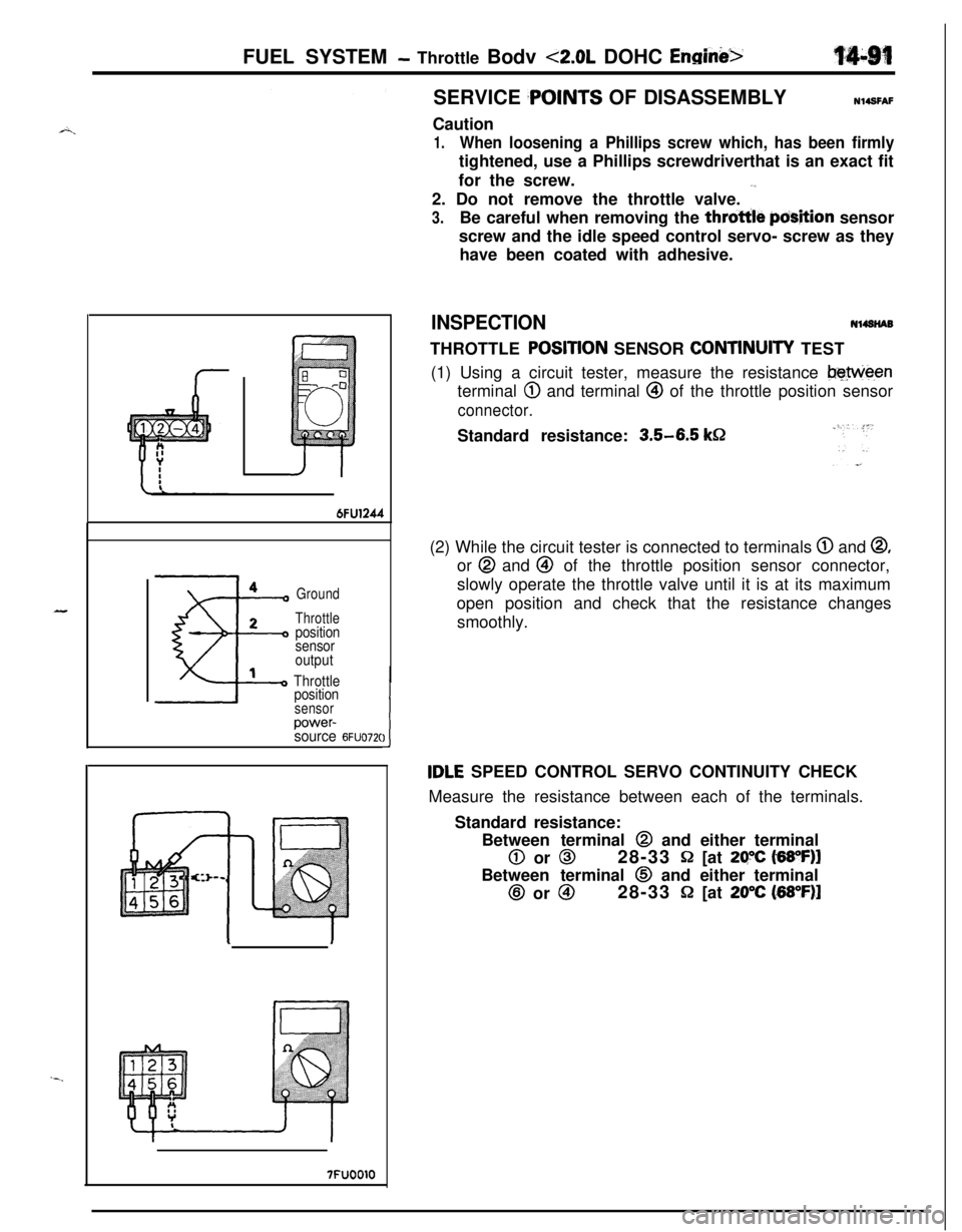
INSPECTIONNl4SNABTHROTTLE
POStTlON SENSOR CONTtNUlTY TEST
(1) Using a circuit tester, measure the resistance
beweenterminal
@ and terminal @ of the throttle position sensor
connector.Standard resistance:
3.5-6.5 k&2(2) While the circuit tester is connected to terminals
@ and @,or @ and @ of the throttle position sensor connector,
slowly operate the throttle valve until it is at its maximum
open position and check that the resistance changes
smoothly.
tDLE SPEED CONTROL SERVO CONTINUITY CHECK
Measure the resistance between each of the terminals.
Standard resistance:
Between terminal @ and either terminal
0 or 028-33 Q [at 29X t6WF)lBetween terminal
0 and either terminal@ or
@I28-33 P [at 20°C (68”F)l
Page 547 of 1216
FUEL SYSTEM - Fuel Tank
FUEL TANK cFWD>
,*. REMOVAL AND INSTALLATION
q?&g
NlMA-30-40 Nm
2-3 Nm22-29 ft.lbs.
---15-20 Nm
11-14 ft.lbs.
15-22 ft.lbs.Removal steps
l + 1. Return hosel +2. Vapor hose
3. Clamp
4. Fuel gauge unit connector
5. Electrical fuel pump connector
l + l q6. High pressure fuel hose
l + 7. Filler hose
l + 8. Vapor hose
~~ 9. Self-locking nut10. Tank band11. Fuel tank
l + 12. Vapor hosel + 13. Overfill limiter (Two-way valve)I)+ 14. Fuel gauge unitl + 15. Electrical fuel pump16. Drain plug
17. Fuel tank cap
18. Packing
19. Fuel filler neck$TEeverse the removal procedures to reinstall,(2) +e : Refer to “Service Points of Removal”:,,
(3) *+ : Refer to “Service Points of lnstallatlon .(4) m : Non-reusable parts
Page 548 of 1216
14-94FUEL SYSTEM - Fuel Tank
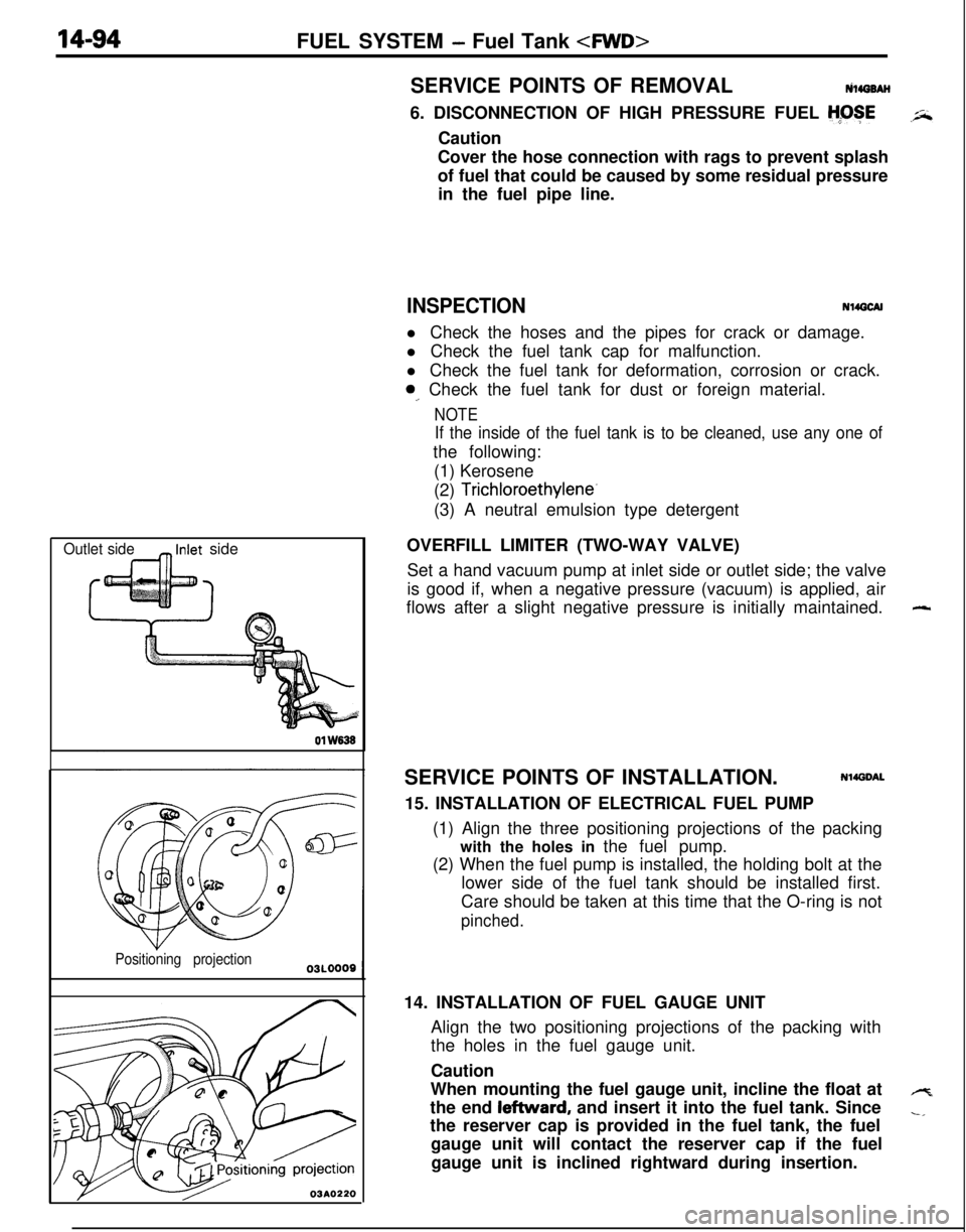
Outlet side_ Inlet side01
W838
Positioning projection
03A0220SERVICE POINTS OF REMOVALtilirro8AH
6. DISCONNECTION OF HIGH PRESSURE FUEL
H;OSECaution
Cover the hose connection with rags to prevent splash
of fuel that could be caused by some residual pressure
in the fuel pipe line.
INSPECTIONN14GCAll Check the hoses and the pipes for crack or damage.
l Check the fuel tank cap for malfunction.
l Check the fuel tank for deformation, corrosion or crack.
0,. Check the fuel tank for dust or foreign material.
NOTE
If the inside of the fuel tank is to be cleaned, use any one ofthe following:
(1) Kerosene
(2)
Trichloroethylene-(3) A neutral emulsion type detergent
OVERFILL LIMITER (TWO-WAY VALVE)
Set a hand vacuum pump at inlet side or outlet side; the valve
is good if, when a negative pressure (vacuum) is applied, air
flows after a slight negative pressure is initially maintained.
SERVICE POINTS OF INSTALLATION.
Nl4DDAL15. INSTALLATION OF ELECTRICAL FUEL PUMP
(1) Align the three positioning projections of the packing
with the holes in the fuel pump.
(2) When the fuel pump is installed, the holding bolt at the
lower side of the fuel tank should be installed first.
Care should be taken at this time that the O-ring is not
pinched.14. INSTALLATION OF FUEL GAUGE UNIT
Align the two positioning projections of the packing with
the holes in the fuel gauge unit.
Caution
When mounting the fuel gauge unit, incline the float at
the end leftward, and insert it into the fuel tank. Since
the reserver cap is provided in the fuel tank, the fuel
gauge unit will contact the reserver cap if the fuel
gauge unit is inclined rightward during insertion.
-
4
-,