Page 559 of 1216

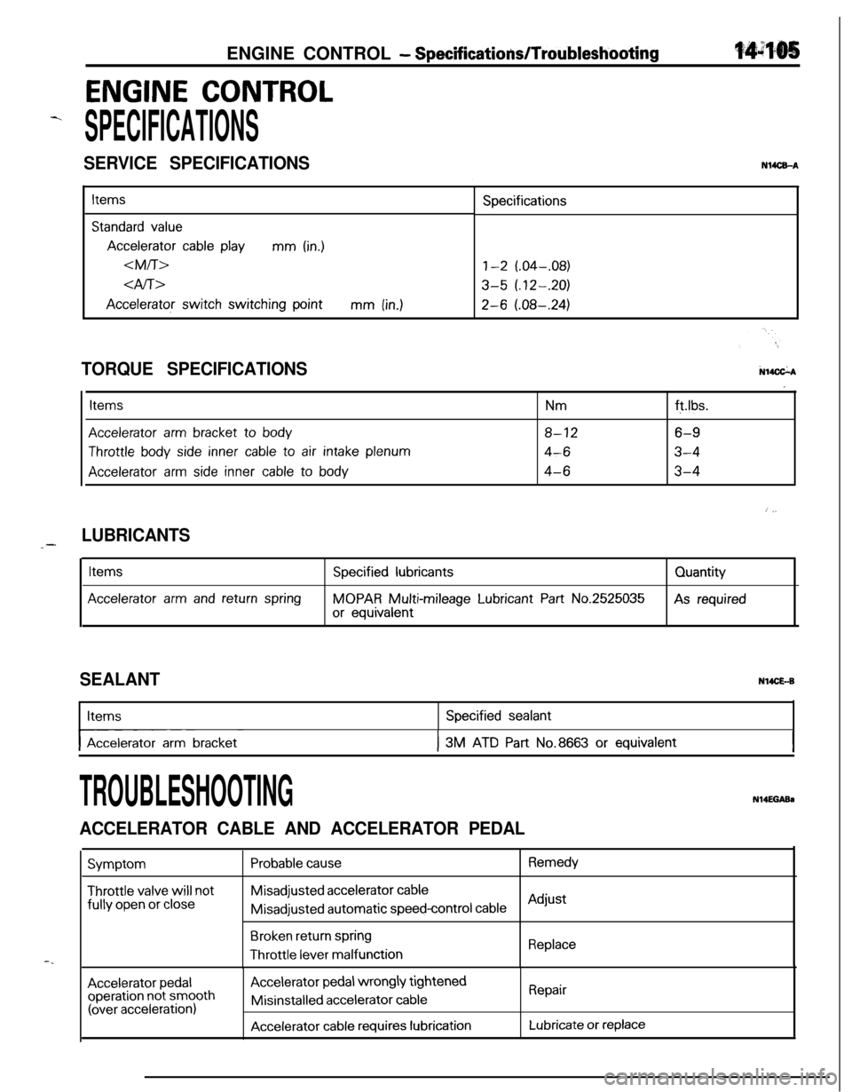
ENGINE CONTROL - SpecificatiodTroubleshooting
ENGINE CONTROL
-.
SPECIFICATIONS
SERVICE SPECIFICATIONSN14CEA
Items
Standard value
Accelerator cable playmm (in.)
dfi>
Accelerator switch switching pointmm (in.)Specifications
1-2 (.04-.08)
3-5 (.12-.20)
2-6 (.08-.24)
N14CkATORQUE SPECIFICATIONS
Items
Accelerator arm bracket to body
Throttle body side inner cable to air intake plenum
Accelerator arm side inner cable to body
Nmft.lbs.
8-126-9
4-63-4
4-63-4
I
: j,
LUBRICANTS_-
Items
Accelerator arm and return spring
Specified lubricants
MOPAR Multi-mileage Lubricant Part No.2525035
or equivalentQuantityAs required
SEALANTN14CE.-BItems
I-- ~Accelerator arm bracket
Specified sealant
I3M ATD Part No.8663 or equivalentI
-.
TROUBLESHOOTINGN14EGABa
ACCELERATOR CABLE AND ACCELERATOR PEDAL
Symptom
Throttle valve will notfully
open or close
Probable causeRemedyMisadjusted
accelerator cableMisadjusted automatic
speed-control cableAdjust
Broken return springThrottle
lever malfunctionReplace
Accelerator pedaloperation not smooth(over acceleration)
Accelerator pedal wrongly tightenedMisinstalled
accelerator cable
Accelerator cable requires lubrication
Repair
Lubricate or replace
Page 560 of 1216

14-106ENGINE CONTROL - Service Adjustment Procedures
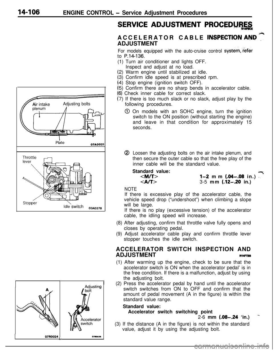
TAir intakeAdjusting bolts
Idle switch03A,,2.8
07RQ024L
I
SERVICE ADJUSTMENT PROCEDM%,&ACCELERATOR CABLE
CNSPECTION AN&I ”ADJUSTMENT
For models equipped with the auto-cruise control systemreferto
P.14-136.(1) Turn air conditioner and lights OFF.
Inspect and adjust at no load.
2) Warm engine until stabilized at idle.
3) Confirm idle speed is at prescribed rpm.
4) Stop engine (ignition switch OFF).
5) Confirm there are no sharp bends in accelerator cable.
6) Check inner cable for correct slack.
7) If there is too much slack or no slack, adjust play by the
following procedures.
@ On models with an SOHC engine, turn the ignition
switch to the ON position (without starting the engine)
and leave in that condition for approximately 15
seconds.@
Loosen the adjusting bolts on the air intake plenum, andthen secure the outer cable so that the free play of the
inner cable will be the standard value.
Standard value:
jlr
l-2 mm (.04-.08 in.) \. *
3-5 mm (.12-.20 in.)
NOTEIf there is excessive play of the accelerator cable, the
vehicle speed drop (“undershoot”) when climbing a slope
will be large.
If there is no play (excessive tension) of the accelerator
cable, the idling speed will increase.
(8) After adjusting, confirm that throttle valve fully opens and
closes by operating pedal.
(9) Adjust accelerator cable play and confirm throttle lever
stopper touches the idle switch.
ACCELERATOR SWITCH INSPECTION AND
ADJUSTMENT
NlWlEB(1) After warming up the engine, check to be sure that the
accelerator switch is ON when the accelerator pedal’ is in
the free condition. If there is a malfunction, adjust by using
the adjusting bolt.
(2) Press the accelerator pedal by hand until the accelerator
switch switches from ON to OFF and confirm that the
amount of pedal movement (A in the figure) is within the
standard value range.
Standard value:
Accelerator switch switching point
2-6 mm
(.08-.24 ‘in.)
(3) If the distance (A in the figure) is not within the standard
value, adjust it by using the adjusting bolt.
Page 561 of 1216
Page 562 of 1216

14-108ENGINE CONTROL - Engine Control
INSPECTION
j N%PJCf@l Check the inner and outer cable for damage.
l Check the cable for smooth movement.$+
l Check the accelerator arm for bending.--
l Check the return spring for deterioration.
l Check the connection of bushing to end metal fitting.
l Check the accelerator switch for ON/OFF switching.
SERVICE POINTS OF INSTALLATIONN14DDAP
ll.APPLlCATlON OF GREASE TO RETURN SPRING/
10. ACCELERATOR ARM
Apply multipurpose grease around the each moving point
of the accelerator arm.
Grease: MOPAR Multi-mileage Lubricant
Part No.2525035 or equivalent
8. APPLICATION OF SEALANT TO ACCELERATOR ARM
BRACKETApply the specified sealant to the bolt mounting hole, and
then tighten the accelerator arm bracket.
,%Specified sealant:
3M ATD Part No.8663 or equivalent
4. APPLICATION OF GREASE TO ACCELERATOR ARM
SIDE INNER CABLE/B. BUSHING
(1) Securely install the resin bushing of the accelerator
cable on the end of the accelerator arm.
(2) Apply multipurpose grease around the cable end.
Grease: MOPAR Multi-mileage Lubricant
Part No.2525035 or equivalent
Page 563 of 1216

AUTO-CRUISE CONTROL SYSTEM - Snecifications14-109
AUTO-CRUISE CONTROL SYSTEM
.-4.
SPECIFICATIONS
GENERAL SPECIFICATIONSNUCA-B
ItemsSpecifications
Auto-cruise control switch
Rated load AMAIN3.OkO.5
SET0.2fO.l
RESUME0.2kO.l
Voltage drop V0.2 or less
Stop light switch
Rated load A0.1-0.9
Voltage drop (at rated load)V0.25 or less
Clutch switch
Rated load A0.005-l
Voltage drop (at rated load)V0.15 or less
Auto-cruise control unit
Range of speed controlkm/h (mph)40 (25)_+3 (1.81-145 (90)_+5 (3.1)
Auto-cruise control actuator
Drive systemVacuum type
Strokemm (in.)38-42 (1.5-I .7)
Auto-cruise vacuum pump
Rated load A0.4 or less
SERVICE SPECIFICATIONSItems
Accelerator cable playmm (in.)
4l-bThrottle
cable playmm (in.)
Auto-cruise cable playmm (in.)
Control valve, Release valve resistanceQ
Specifications
O-l (O-.04)
2-3 (.08-,121
1-2 (.04-.08)
1-2 (.04-.08)
50-60
TORQUE SPECIFICATIONSN14CGCItems
Nmftlbs.
Link protector4-63-4-.
Link assembly9-147-10
Auto-cruise vacuum pump4-63-4
Accelerator cable plate4-63-4
Page 589 of 1216

AUTO-CRUISE CONTROL SYSTEM L service Adjustkt Procedw&
03A0258
YSET
03AO258
03AO250
SET
03A025t
JI
SERVICE ADJUSTMENT PROCEDURESNl4FUU
AUTO-CRUISE CONTROL SYSTEM INSPECTION
AUTO-CRUISE CONTROL SWITCH CHECK(1) Turn the ignition key to ON.
(2) Check to be sure that the indicator light within the switch
illuminates when the cruise control switch is switched ON.
(Turn the cruise control switch to the “CRUISE” position.)
AUTO-CRUISE CONTROL SETTING CHECK(1) Switch ON the cruise control switch.
(2) Drive at the desired speed within the range of approxi-
mately 40-145 km/h (25-90 mph).
(3) Press the SET button.
(4) Check to be sure that the speed is the desired constant
speed when the switch is released, and also check to be
sure that the auto cruise indicator light (tithin the combina-tion meter) illuminates.
NOTE1(
If the vehicle speed decreases to approximately 15 km/h
(9 mph) below the set speed, because of climbing a hill for
example, the auto-cruise control will be
cancelled.
SPEED-INCREASE SETTING CHECK
(‘1) Set to the desird speed.
(2) Turn the control switch to RESUME position.
(3) Check to be sure that acceleration continues while the
switch is hold, and that when it is released the constant
speed at the time when it was released becomes the
driving speed.
NOTEEven if, during acceleration, the vehicle speed reaches or
exceeds the high limit [approximately 145 km/h (90
mph)], acceleration will continue, however, when the
switch is released, the set speed (“memorized speed”) will
become the high limit of the vehicle speed.
’ ” ,
SPEED REDUCTION SETTING CHECK(1) Set to the desired speed.
(2) Press the SET button.
(3) Check to be sure that deceleration continues while the
switch is pressed, and that when it is released the
constant speed at the time when it was released becomes
the driving speed.
NOTEIWhen the vehicle speed reaches the low limit [approxi-
mately 40 km/h (25 mph)] during deceleration, the auto-
matic speed control will be
cancelled.
Page 590 of 1216
Page 591 of 1216

AUTO-CRUISE CONTROL SYSTEM - Service Adjustment Procedures
Stopper13A0360
13A0361
2OAO402
lBAOlS2(5) Adjust with adjusting nut A so when link A hits the stopper,
the accelerator cable play (inner cable play) reaches the
standard value.
Standard valueM/T: O-l mm
(O-.04 in.)
A/T: 2-3 mm (.08-.12
in.)(6)
Fix the accelerator cable with the lock nut.
(7) Adjust with adjusting nut
B so when the link B stopper hits
the end of link A, throttle cable play (inner cable play)
reaches the standard value.
Standard value:
l-2 mm (.04-.08 in.)
(8) Fix the throttle cable with lock nut and adjusting bolt
D.‘(9) Adjust with.adjusting nut
C so when the link C stopper hits
the end of link B, the auto-cruise control cable play (inner
cable play) reaches the standard value.
Standard value:
l-2 mm (.04-.08 in.)
(lO)Fix the auto-cruise control cable with the lock nut.
(1 l)After adjusting, confirm that throttle valve fully opens and
closes by operating pedal.
INDIVIDUAL PARTS INSPECTION
AUTO-CRUISE CONTROL SWITCH INSPECTION(1) Remove the knee protector assembly and the lower
column cover.
(2) Disconnect the column switch connector and check the
continuity between the terminals.
O-0: continuity
NeutralRESUME switch ON00
NOTEIf there is an abnormal condition (any condition not described in the
table above), replace the column switch.