1991 MITSUBISHI ECLIPSE service
[x] Cancel search: servicePage 505 of 1216
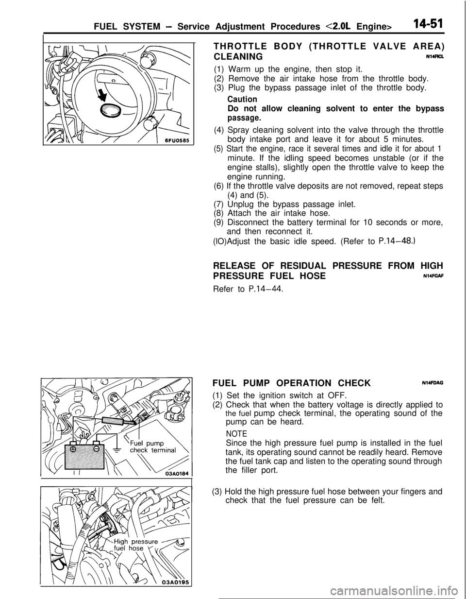
FUEL SYSTEM - Service Adjustment Procedures <2.0L Engine>14-51THROTTLE BODY (THROTTLE VALVE AREA)
CLEANINGNl4FtU
(1) Warm up the engine, then stop it.
(2) Remove the air intake hose from the throttle body.
(3) Plug the bypass passage inlet of the throttle body.
CautionDo not allow cleaning solvent to enter the bypass
passage.(4) Spray cleaning solvent into the valve through the throttle
body intake port and leave it for about 5 minutes.
(5) Start the engine, race it several times and idle it for about 1minute. If the idling speed becomes unstable (or if the
engine stalls), slightly open the throttle valve to keep the
engine running.
(6) If the throttle valve deposits are not removed, repeat steps
(4) and (5).
(7) Unplug the bypass passage inlet.
(8) Attach the air intake hose.
(9) Disconnect the battery terminal for 10 seconds or more,
and then reconnect it.
(lO)Adjust the basic idle speed. (Refer to P.14-48.)
RELEASE OF RESIDUAL PRESSURE FROM HIGH
PRESSURE FUEL HOSE
N14FGAFRefer to
P.14-44.FUEL PUMP OPERATION CHECK
N14FDAG(1) Set the ignition switch at OFF.
(2) Check that when the battery voltage is directly applied to
the fuel pump check terminal, the operating sound of the
pump can be heard.
NOTESince the high pressure fuel pump is installed in the fuel
tank, its operating sound cannot be readily heard. Remove
the fuel tank cap and listen to the operating sound through
the filler port.
I(3) Hold the high pressure fuel hose between your fingers and
check that the fuel pressure can be felt.
Page 506 of 1216
14-52FUEL SYSTEM - Service Adjustment Procedures <2.0L Engine>
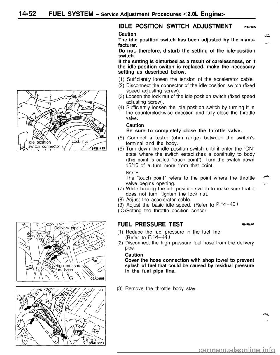
IDLE POSITION SWITCH ADJUSTMENT
Caution
N14UDAThe idle position switch has been adjusted by the manu-
facturer.Do not, therefore, disturb the setting of the idle-position
switch.
If the setting is disturbed as a result of carelessness, or if
the idle-position switch is replaced, make the necessary
setting as described below.
(1) Sufficiently loosen the tension of the accelerator cable.
(2) Disconnect the connector of the idle position switch (fixed
speed adjusting screw).
(3) Loosen the lock nut of the idle position switch (fixed speed
adjusting screw).
(4) Sufficiently loosen the idle position switch by turning it in
the counterclockwise direction and fully close the throttle
valve.Caution
Be sure to completely close the throttle valve.
(5) Connect a tester (ohm range) between the switch’s
terminal and the body.
(6) Turn down the idle position switch until it enter the “ON”
state where the switch establishes a continuity to body
(this point is called “touch point”). Turn the switch down
15/16 of a turn more from that point.
NOTEThe “touch point” refers to the point where the throttle
valve begins opening.
(7) While holding the idle position switch to make sure that it
does not turn, tighten the lock nut.
(8) Adjust the accelerator cable.
(9) Adjust the basic idle speed. (Refer to P.14-48.)
(lO)Setting the throttle position sensor.
FUEL PRESSURE TESTN14FNAO(1) Reduce the fuel pressure in the fuel line.
(Refer to
P.14-44.)(2) Disconnect the high pressure fuel hose from the delivery
pipe.Caution
Cover the hose connection with shop towel to prevent
splash of fuel that could be caused by residual pressurein the fuel pipe line.
(3) Remove the throttle body stay.
Page 507 of 1216
FUEL SYSTEM - Service Adjustment Procedures <2.0L Enaine>14-53
MD998709
MD998742
I
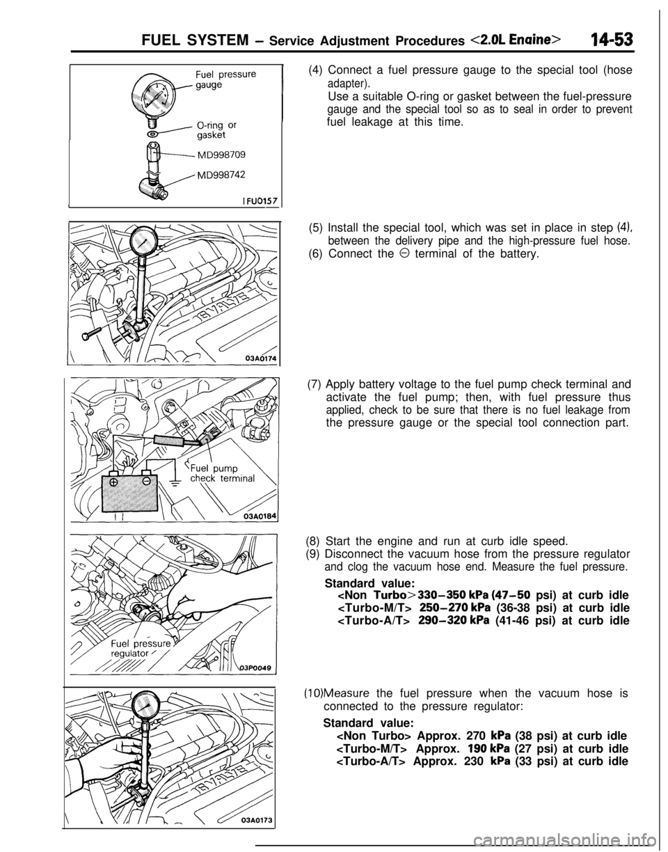
FU01571-(4) Connect a fuel pressure gauge to the special tool (hose
adapter).Use a suitable O-ring or gasket between the fuel-pressure
gauge and the special tool so as to seal in order to preventfuel leakage at this time.
(5) Install the special tool, which was set in place in step
(4),
between the delivery pipe and the high-pressure fuel hose.(6) Connect the
0 terminal of the battery.
(7) Apply battery voltage to the fuel pump check terminal and
activate the fuel pump; then, with fuel pressure thus
applied, check to be sure that there is no fuel leakage fromthe pressure gauge or the special tool connection part.
(8) Start the engine and run at curb idle speed.
(9) Disconnect the vacuum hose from the pressure regulator
and clog the vacuum hose end. Measure the fuel pressure.Standard value:
250-270 kPa (36-38 psi) at curb idle
290-320 kPa (41-46 psi) at curb idle
(10)Measure the fuel pressure when the vacuum hose is
connected to the pressure regulator:
Standard value:
kPa (38 psi) at curb idle
190 kPa (27 psi) at curb idle
kPa (33 psi) at curb idle
Page 508 of 1216
14-54FUEL SYSTEM - Service Adjustment Procedures <2.0L Engine>
(11)Race the engine repeatedly in two or three series. Then
check that the fuel pressure does not fall when the engine
is running at idle.
(12)Check to be sure that there is fuel pressure in the return
hose also (by gently pressing the fuel return hose with a
finger while repeatedly racing the engine).
NOTEThere will be no fuel pressure in the return hose when the
volume of fuel flow is not sufficient.
(13)lf the results of the measurements made in steps (9) and
(10) above are not within the standard value, use the table
below to determine the probable cause, and then make the
necessary repair.
Condition
Fuel pressure too lowProbable causeRemedy
a. Clogged fuel filtera. Replace fuel filter.
b. Fuel leaking toward return port due tob. Replace fuel pressure regulator.
improper seating of valve in fuel pressure
regulator
c. Low delivery pressure of fuel pumpc. Replace fuel pump.
Fuel pressure too higha. Stuck valve in fuel pressure
a. Replace fuel pressure regulator.regulator
b. Clogged or bent fuel return hose or pipeb. Repair or replace hose or pipe.
Fuel pressure witha. Clogged or broken vacuum hose or nipplea. Repair or replace vacuum hose or
vacuum hose connected
nipple.
not different from fuel
pressure with vacuumb. Stuck valve in fuel pressure regulator or
b. Replace fuel pressure regulator.
hose not connecteddefective valve seating
(14)Stop the engine and check for change in fuel pressure
gauge indication, which should not drop.
If the gauge indication drops, observe the rate of drop and
determine and remove the causes according to the
following table.
Condition
Fuel pressure drops
slowly after engine is
stopped.Probable cause
Leakage from injectorRemedy
Replace injector.
Fuel pressure drops
im-Check valve in fuel pump does not closeReplace fuel pump.
mediately after engine is
stopped.
(15)Reduce the fuel pressure in the fuel line.
(16)Disconnect the high pressure fuel hose and remove the
fuel-pressure gauge from the delivery pipe.
Caution
Cover the hose connection with shop towel to prevent
splash of fuel that could be caused by residual pressurein the fuel pipe line.
(17)Mount a new O-ring in the groove at the end of the high
pressure fuel hose.
Page 509 of 1216
FUEL SYSTEM - Service Adjustment Procedures <2.0L Engine>14-55
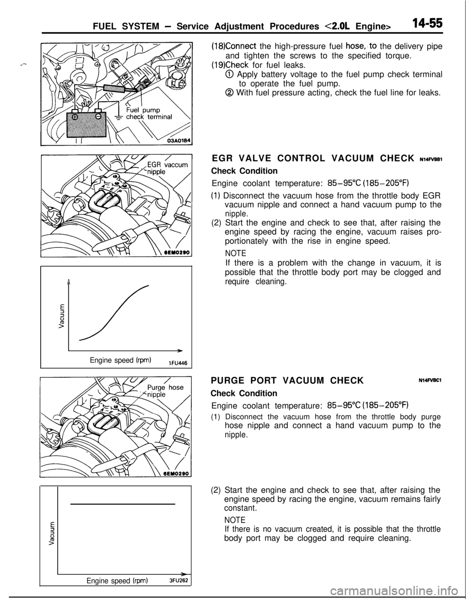
(18)Connect the high-pressure fuel hose,,to the delivery pipe
and tighten the screws to the specified torque.
(19)Check for fuel leaks.
@I Apply battery voltage to the fuel pump check terminal
to operate the fuel pump.
@ With fuel pressure acting, check the fuel line for leaks.
A
E2li:>
/ )
Engine speed (rpm)lFU4l6EGR VALVE CONTROL VACUUM CHECK
NlQFVBBlCheck Condition
Engine coolant temperature:
85-95°C (185-205°F)
(1) Disconnect the vacuum hose from the throttle body EGR
vacuum nipple and connect a hand vacuum pump to the
nipple.(2) Start the engine and check to see that, after raising the
engine speed by racing the engine, vacuum raises pro-
portionately with the rise in engine speed.
NOTEIf there is a problem with the change in vacuum, it is
possible that the throttle body port may be clogged and
require cleaning.PURGE PORT VACUUM CHECK
Check Condition
N14FVBClEngine coolant temperature:
85-95°C (185-205°F)
(1) Disconnect the vacuum hose from the throttle body purge
hose nipple and connect a hand vacuum pump to the
nipple.
Engine speed (rpm)3FU262(2) Start the engine and check to see that, after raising the
engine speed by racing the engine, vacuum remains fairly
constant.
NOTE
If there is no vacuum created, it is possible that the throttlebody port may be clogged and require cleaning.
Page 519 of 1216

FUEL SYSTEM - MPI Svstem InsDection <1.8L Engine>14-65
3FUO349
/--
’ 3FU03991
Idle speed controlservo connector(motor side, front view)
3FUO393
INHIBITOR SWITCHN14QRACsRefer to GROUP 21
- Service Adjustment Procedures.
POWER STEERING OIL PRESSURE SWITCH
N14flCJBRefer to GROUP 19 for power steering system inspection.
INJECTORSN14QTAGCHECKING OPERATION SOUND
Using a sound-scope, check the operation sound (“chi-chi-chi”)of injectors during idling or during cranking.
Check that as the rotating speed increases, the frequency of
the operating sound also increases.
Caution
Note that even if the injector you are checking is not
operating, you will hear the operating sound of the other
injectors.
NOTEIf no operating sound is heard from the injector that is being
checked, check the injector drive circuit. If there is nothing
wrong with the circuit, a defective injector or engine control
unit is suspected.
MEASURING RESISTANCE BETWEEN TERMINALS
(1) Remove the injector connector.
(2) Measure the resistance between the terminals.
Standard value: 13
- 16 L(Z [at 20°C (68”F)I(3) Install the injector connector.
IDLE SPEED CONTROL SERVO
INSPECTION
NlQQUAAb(1) Disconnect the idle speed control servo connector.
(2) Check continuity of the idle speed control servo coil.
IMeasuring terminalsIContinuityI
@ - @ Conductive5 to 35 fi resistance
at 20°C (68°F)
Page 537 of 1216

INJECTORFUEL SYSTEM
- Injector14-83
* ‘- REMOVAL AND INSTALLATIONNWSA-A
Post-installation Operation
l Measurement of Fuel Pressure(Refer to P.14-44. 52.)
4.8L Engine><2.0L DOHC
Engilme>11R7-11 Nm
-hl ft.lbs.-zF!
;533i5,b;m-. .-Y-71s4-6 Nma-3-4 ft.lbs.
03AOlSS::,
4*12:
Center cover
Connection for control harness
Delivery pipe
d-- -13. Insulator4-6 Nm
3-4
ft.lbs.
lo-13 Nm
7-9 ft.lbs.Removal steps
1. Connection for breather hose
2. Connection for PCV hose
+e *+3. Connection for high pressure fuel hose
4. O-ring
5. Connection for vacuum hose6. Connection for fuel return hose
l + 7. Fuel pressure regulator8. O-ring
9. Accelerator cable clamp
03AO19014. Insulator
** l + 15. InjectorH 16. O-ringl + 17. Grommet
!PTkeverse the rem&al procedures to reinstall.(2) +* : Refer to “Service Points of Removal”.
(3) l * : Refer to “Service Points of Installatron”(4) m : Non-reusable parts
Page 538 of 1216
14-84FUEL SYSTEM - Injector
03*0095
Delivery pipe03A0095-SERVICE POINTS OF REMOVAL
H4s0m1‘~
3.DISCONNECTION OF THE HIGH PRESSURE FlJFL HOSE /;;
Bleed the residual pressure within the fuel pipe line’& as to~prevent the flow of fuel.
For information concerning the method to be folfowed for
bleeding the residual pressure, refer to
P.14-44.Caution
Cover the hose connection with rags to prevent splash,
of fuel that could be caused by some residual pressure
in the fuel pipe line.
12. REMOVAL OF DELIVERY PIPE/ 15. INJECTOR
Remove the deliver-y pipe (with the injectors attached to it).Caution
Care must be taken, when removing the delivery pipe,
not to drop the injector.
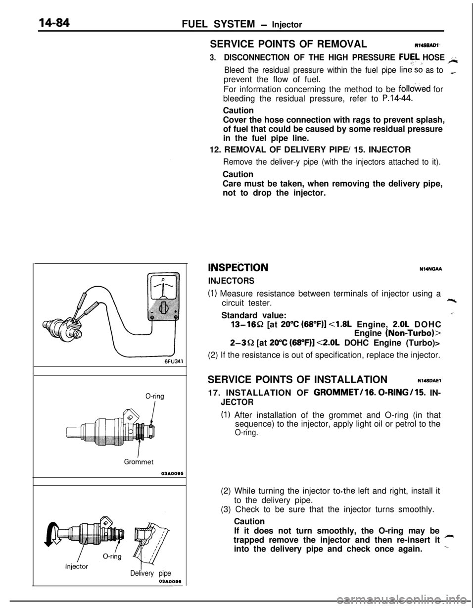
INSPEiZTION
INJECTORS
N14NGAA
(1) Measure resistance between terminals of injector using a
circuit tester.+-%Standard value:
/13-1652 [at
20°C (68”F)] <1.8L Engine, 2.0L DOHC
Engine
(NoniTurbo)>
2-3Q [at 20°C (68”F)] <2.0L DOHC Engine (Turbo)>
(2) If the resistance is out of specification, replace the injector.
SERVICE POINTS OF INSTALLATION
N14SDAEl’17. INSTALLATION OF
GROMMET/lG. 0-RINGI15. IN-
JECTOR
(I) After installation of the grommet and O-ring (in that
sequence) to the injector, apply light oil or petrol to the
O-ring.(2) While turning the injector to.the left and right, install it
to the delivery pipe.
(3) Check to be sure that the injector turns smoothly.
Caution
If it does not turn smoothly, the O-ring may be
~trapped remove the injector and then re-insert it
into the delivery pipe and check once again.
L