Page 1083 of 1216
BODY - Front Bumper
FRONT BUMPER
- REMOVAL AND INSTALLATION
< Normal type >
23-39
N232AAU35-55 Nm25-40
ft.lbs.
”18A0725
Front bumper assembly removal steps1. Splash shield mounting clip
a*2. Front garnish
3. Front turn signal light
4. Front combination light
5. Air intake cover
6. Front bumper assembly
7. Fascia upper plate
8. Front bumper reinforcement assembly
9. Front bumper fascia
Front bumper fascia removal steps
1. Splash shield mounting clip
**2. Front garnish
3. Front turn signal light
4. Front combination light
5. Air intake cover
7. Fascia upper plate
9. Front bumper fascia
NOTE
(I 1 Reverse the removal procedures to reinstall.(2) 4, : Refer to “Service Points of Removal”.
(3)l :
SERVICE POINTS OF REMOVAL2. REMOVAL OF FRONT GARNISH
Refer to
P.23-47.
Page 1084 of 1216
23-40BODY - Front Bumper
c Large type >
35-44 Nm
25-32
ft.lbs.
c4WA0726
Front bumper assembly removal steps
1, Splash shield mounting clip
4*2. Front garnish
3. Front turn signal light
4. Front combination light
5. Front fog light
6. Fog light bracket
7. Front bumper assembly
8. Fascia upper plate
9. Front bumper reinforcement assembly
10. Front bumper fascia
Front bumper fascia removal steps1. Splash shield mounting clip
4*2. Front garnish3. Front turn signal light
4. Front combination light
5. Front fog light
8. Fascia upper plate
10. Front bumper fasciaFr)?everse
the removal procedures to reinstall.- (2) +I) : Refer to “Service Points of Removal”.
SERVICE POINTS OF REMOVAL
2. REMOVAL OF FRONT GARNISH
Refer to P.23-47.
Page 1095 of 1216

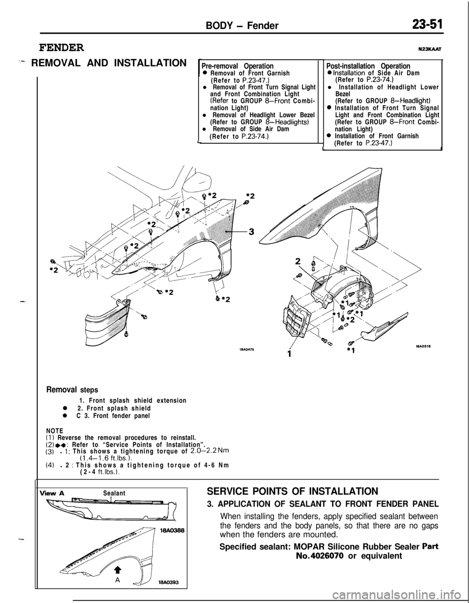
BODY - Fender
FENDER
:- REMOVAL AND INSTALLATION
-.
Pre-removal Operation0 Removal of Front Garnish
(Refer to P.23-47.)l Removal of Front Turn Signal Light
and Front Combination Light
(Refer to GROUP 8-Front Combi-
nation Light)
l Removal of Headlight Lower Bezel
(Refer to GROUP
8-Headlights)l Removal of Side Air Dam
(Refer to
P.23-74.)LLu23KAAr
Post-installation Operation0 Installation of Side Air Dam
(Refer to P.23-74.)l Installation of Headlight Lower
Bezel
(Refer to GROUP
8-Headlight)0 Installation of Front Turn Signal
Light and Front Combination Light
(Refer to GROUP
8-Front Combi-
nation Light)
0 Installation of Front Garnish
(Refer to P.23-47.)J
Removal steps1. Front splash shield extension
l 2. Front splash shield
l C 3. Front fender panel
NOTE
(1) Reverse the removal procedures to reinstall.(2) .a : Refer to “Service Points of Installation”.
(3)l 1 : This shows a tightening torque of 2.0-2.2 Nm(1 .4-l .6 ft.lbs.1.(4)l 2 : This shows a tightening torque of 4-6 Nm
(2-4 ft.lbs.1.
View ASealantSERVICE POINTS OF INSTALLATION
3. APPLICATION OF SEALANT TO FRONT FENDER PANEL
When installing the fenders, apply specified sealant between
the fenders and the body panels, so that there are no gapswhen the fenders are mounted.
Specified sealant: MOPAR Silicone Rubber Sealer
PartNo.4026070 or equivalent
Page:
< prev 1-8 9-16 17-24