Page 273 of 1216
COOLING - Water Hose and Water Pipe <1.8L Engine>
WATER HOSE AND WATER PIPE
<1.8L Engine>
_-REMOVAL AND INSTALLATIONNO’IIA-A27-33 Nm
20-24 ftlbs.
12-15 Nms- 11 ft.lbs.Removal steps
1 Air intake hose
2. Engine oil level gauge guide3. O-ring
4. Self locking nut
5. Gasket
6. Oxygen sensor harness connector
7. Exhaust manifold cover (A)
8. Engine hanger9. Exhaust manifold
IO. Exhaust manifold gasket
11. Exhaust manifold cover(B)NOTE(1) Reverse the removal procedures to reinstall.(2) m : Non-reusable parts
Page 279 of 1216

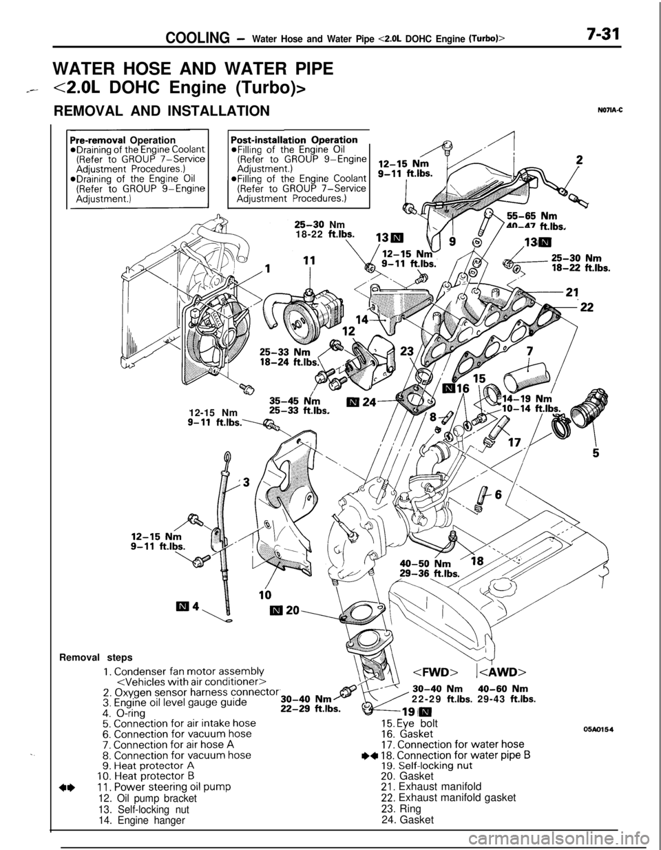
COOLING -Water Hose and Water Pipe <2.0L DOHC Engine (Turbo)>7-31WATER HOSE AND WATER PIPE
7--<2.0L DOHC Engine (Turbo)>
REMOVAL AND INSTALLATION
N071A-C
. .
ation OperationPost-installi@Filling of the Engine Oil(Refer to GROUP g-EngineaFilling of the
Engine Coolant(Refer to GROUP 7-ServiceAdjustment Procedures.)
Pre-removal OperationeDraining of the Engine Coolant(Refer to GROUP 7-ServiceAdjustment Procedures.)*Draining of the Engine Oil(Refer to GROUP g-Engine
25-30 Nm
18-22 ftlbs.4n-47 ft.lbs.
w35-45 N/m12-15 Nm25-33 ft.lbs.
9- 11ft.lbs.----Q&Removal steps
1. Condenser fan motor assembly2. Oxygen sensor harness connector3. Engine oil level gauge guide4. O-ring5. Connection for air intake hose6. Connection for vacuum hose7. Connection for air hose A8. Connection for vacuum hose9. Heat protector A10. Heat protector B
4*11. Power steering oil pump
12. Oil pump bracket
13. Self-locking nut
14. Engine hanger22-29
ft.lbs. 29-43 ft.lbs.
15. Eye bolt16. Gasket17. Connection for water hose
I)+ 18. Connection for water pipe B19. Self-locking nut20. Gasket21. Exhaust manifold22. Exhaust manifold gasket
23. Ring
24. Gasket
05m154
Page 307 of 1216

ENGINE - Troubleshooting9-23
--Symptom
Compression too lowProbable cause
Cylinder head gasket blown
Piston ring worn or damage
Piston or cylinder wornRemedy
Replace gasket
Replace rings
Repair or replace piston and/or cylinder
block
Valve seat worn or damageRepair or replace valve and/or seat ring
Oil pressure dropEngine oil level too lowCheck engine oil level
Oil pressure switch faultyReplace oil pressure switch
Oil filter cloggedInstall new filter
Oil pump gears or cover wornReplace gears and/or cover
Thin or diluted engine oilChange engine oil to correct viscosity
Oil relief valve stuck (opened)Repair relief valve
Excessive bearing clearanceReplace bearings
Oil pressure too highOil relief valve stuck (closed)Repair relief valve
Noisy valvesIncorrect lash adjusterBleed air or replace lash adjuster
Thin or diluted engine oil (low oil pressure)Change engine oil
Valve stem or valve guide worn or damageReplace valve and/or guide
Connecting rod noise/Insufficient oil supplyCheck engine oil level
main bearing noise
Low oil pressureRefer to “Oil pressure drop”
Thin or diluted engine oilChange engine oil
Excessive bearing clearanceReplace bearings
Timing belt noiseIncorrect belt tensionAdjust belt tension
Excessive engine rollingLoose engine roll stopper (Front, Rear)Retighten
and vibration
Loose transaxle mount bracket
Loose engine mount bracket
Loose center member
Broken transaxle mount insulatorReplace
Broken engine mount insulator
Broken engine roll stopper insulator
Page 356 of 1216

9-72ENGINE <1.8L Engine> -Crankshaft, Flywheel and Drive Plate/Cylinder Block
PressOil seal
I
MD99801 1
/
Oil seal case1 EN06L
CYLINDER BLOCK
i//
199.
INSTALLATlON OF REAR OIL SEAL
Install oil seal in the crankshaft rear oil seal case. Using the
special tool, press fit the oil seal all the way in without tiltingiii
it.DISASSEMBLY AND REASSEMBLY
FORWARD
50-70 Nm37-50 ft.lbs.
30-42 Nm22-30 ft.lbs.
NDBVF-A
110-130 Nm80-94 ft.lbs.1. Exhaust pipe support bracket
2. Front roll stopper bracket
3. Rear roll stopper bracket
4. Left engine support bracket5. Cylinder block6. Engine mount bracket
3EN0092
INSPECTIONl Visually check the cylinder block for scores, rust and
corrosion. Also check for cracks or any other faults by using
the magnaflux method. Correct or replace the block if
faulty.
lMeasure the cylinder bore with a cylinder gauge at three
levels and in two directions A and
B as shown. If
out-of-round or taper is more than specified or if the
cylinder walls are badly scuffed or scored, the cylinder
&block should be rebored and honed, and new oversize
_pistons and rings fitted.
Measuring points are as shown.
Cylinder bore: 80.8 mm (3.173 in.)
Out-of-round and taper: 0.01 mm (.0004 in.)
Page 425 of 1216

--
INTAKE AND EXHAUST - SDecificationsII-3
ItemsIntake manifold
<1.8L Engine>
Accelerator cable to air intake plenum
Fuel high pressure hose to delivery pipe
Delivery pipe to intake manifold
Intake manifold stay
Engine hanger
Intake manifold to engine
Throttle body
Air intake plenum stay
Air intake plenum to intake manifold
Water outlet fitting
EGR valveEGR temperature sensor
Ground cable to air intake plenum
Control harness protector to air intake plenum
CoverIntake manifold
<2.0L DOHC Engine>
Accelerator cable to intake manifold
Throttle body stay
Fuel high pressure hose to delivery pipe
Delivery pipe to engine
Intake manifold stay
Intake manifold to engine
Mounting bolt
(M8)Mounting nut and bolt (MIO)
Ignition coil
Power transistor unit
Throttle body
EGR valveEGR temperature sensor
Control harness protector to intake manifold
Control harness clamp bolt
ixhaust manifold
<1.8L Engine>
Front exhaust pipe to exhaust manifold
Front exhaust pipe to engine
Exhaust manifold cover (A) to exhaust manifold
Exhaust manifold cover (B) to exhaust manifold
Exhaust manifold cover (A) to exhaust manifold cover (B)
Exhaust manifold to engine
Oxygen sensor
Engine oil level gauge guide mounting bolt
ixhaust manifold
<2.0L DOHC Engine (Non-Turbo)>
Front exhaust pipe to exhaust manifold
Front exhaust pipe to engine
Heat protector (A), (B)
Exhaust manifold to engine
Oxygen sensor
Engine hanger to engine
ixhaust manifold and turbocharger
<2.0L DOHC Engine (Turbo)>
Front exhaust pipe to exhaust fitting
Front exhaust pipe to engine
Heat protector (A),
(B)
Nmft.lbs.
4-6
3-4
4-6
3-4
IO-137-9
18-25
13-18
15-20II-14
15-2011-14
15-22II-16
15-2011-14
15-2011-14
17-2012-14
IO-157-11
IO-127-9
10-127-9
4-6
3-4
IO-137-9
4-6
3-4
15-22
11-16
4-6
3-4
IO-137-9
25-3018-22
15-2011-14
30-4222-30
20-2714-20
IO-127-9
15-22
11-16
15-22II-16
IO-127-9
4-6
3-4
IO-127-9
30-4022-29
30-4022-29
27-33
20-24
20-2814-20
8-106-7
15-2011-14
40-5029-36
12-15
9-l 1
30-4022-29
30-4022-29
12-15
9-l 1
25-3018-22
40-5029-36
12-15
9-l 1
40-6029-43
30-4022-29
12-15
9-11
Page 426 of 1216

11-4INTAKE AND EXHAUST- Specifications/Special Tool/Troubleshooting
ItemsEngine oil level gauge guide mounting bolt
Engine hanger to engine
Exhaust manifold to engine
Exhaust manifold to turbocharger
Oil pipe to engine
Water pipe
(B) to water inlet pipe
Waste gate actuator
Oxygen sensor
Water pipe
(B) to turbocharger
Air outlet fitting
Oil pipe to turbocharger
Water pipe (A) to turbocharger
Water pipe (A) mounting bolt
Exhaust fitting
Oil return pipe
Exhaust pipe and main muffler
Front exhaust pipe to exhaust manifold
Front exhaust pipe to exhaust fitting
Front exhaust pipe clamp
Rubber hangerFront exhaust pipe to catalytic converter
Catalytic converter to center exhaust pipe
Hanger bracket to body
Hook to center exhaust pipe
Center exhaust pipe to main muffler
Moulding to main muffler
Nmft.lbs.
12-15
9-l 112-159-11
25-3018-?255-65
40-4714-19
IO-l+
40-5029-36
IO-137-9
40-5029-36
35-5025-36
9-14
7-1028-34
20-25
35-5025-36
IO-127-9
55-65
40-47
8-106-7
30-4022-29
40-6029-43
30-4022-29
IO-157-11
40-6029-43
30-4022-29
10-157-11
10-157-11
30-4022-29
4-63-4
TROUBLESHOOTINGNllEAAB
Symptom
Exhaust gas leakage
Abnormal noiseProbable cause
Loose joints
Broken pipe or muffler
Broken separator in muffler
Broken rubber hangersInterference of pipe or muffler with vehicle body
Broken pipe or mufflerRemedy
Retighten
Repair or replace
Replace
Correct
Repair or replace
.-*
SPECIAL TOOLNllDA-
I ToolNumberNameI UseIRemoval/Installation of oxygen sensor
Removal/Installation of oxygen sensor
Fs\
Page 442 of 1216

II-20INTAKE AND EXHAUST - Turbocharger
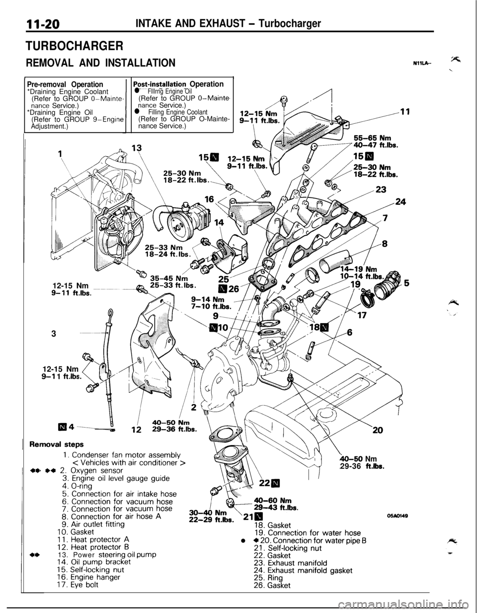
TURBOCHARGER
REMOVAL AND INSTALLATION
II
NHLA-
Pre-removal Operation*Draining Engine Coolant
(Refer to GROUP
0-Maintenance Service.)
*Draining Engine Oil
(Refer to GROUP g-Engine
Adjustment.)1
Po+installation Operationl Flllrng Engine Oil(Refer to GROUP O-Main@
nance Service.)l Filling Engine Coolant(Refer to GROUP O-Mainte-
nance Service.)
12-15 Nm12-15 Nm
9- 11ft.lbs.3
12-15 Nm
9-l 1 ftlbs
moval steps
1. Condenser fan motor assembly< Vehicles with air conditioner >) *4 2. Oxygen sensor3. Engine oil level gauge guide4. O-ring
5. Connection for air intake hose6. Connection for vacuum hose7. Connection for vacuum hose8. Connection for air hose A9. Air outlet fitting
10.Gasket1 1.Heat protector A12. Heat protector B13. Power steering oil pump14. Oil pump bracket15.Self-locking nut16.Engine hanger17.Eye bolt
h-50 Nm29-36 ft.lbs.
19. Connection for water hosel * 20. Connection for water pipe f321. Self-locking nut22. Gasket23. Exhaust manifold24. Exhaust manifold gasket25. Ring26. Gasket
05M1149
Page 448 of 1216

1 I-26INTAKE AND EXHAUST -Exhaust Manifold c 1.8L Engine>
EXHAUST MANIFOLD
< 1.8L Engine>
REMOVAL AND INSTALLATION
20-24 ft.lbs.
05A0135Removal steps’
1. Engine oil level gauge guide
2. O-ring3. Self locking nut4. Gasket5. Oxygen sensor6. Exhaust manifold cover (A)
7. Engine hanger8. Exhaust manifold9. Exhaust manifold gasket10. Exhaust manifold cover (B)
NOTE(1) Reverse the removal procedures to reinstall.(2) 4, : Refer to “Service Points of Removal”.(3) q : Non-reusable parts
SERVICE POINTS OF REMOVALNHNBAG5. REMOVAL OF OXYGEN SENSOR
Disconnect the connector of the oxygen sensor, and install
the special tool to the oxygen sensor.
Then, using an offset (box-end) wrench, remove the oxygen
sensor.
INSPECTIONNllNCALO
Check the following points; replace the part if a problem is
found.-y=.EXHAUST MANIFOLD
Check for damage or cracking of any part.EXHAUST MANIFOLD GASKET
Check for flaking or damage of the gasket.
O-ring
3EN239
or blockage.
5. Clean the inlet section of the compressor cover with a rag.
Inspect it for signs of contact with the compressor turbine.
If worn, replace it.WASTE GATE ACTUATOR
1.Leak-test the waste gate valve actuator with a hand vacuum
pump.
Replace the actuator if it does not hold vacuum.
2. Check the rod to see that it is not bent or binding.
SERVICE POINTS OF REASSEMBLYNllLHAB
7. INSTALLATION OF O-RING
Coat the inner surface of a new O-ring with a thin film of
engine oil, and set it in the groove of the cartridge assembly.
Caution+%
Be careful not to damage the O-ring while installing it as__
oil leakage could result.