1991 MITSUBISHI ECLIPSE oil level
[x] Cancel search: oil levelPage 831 of 1216

AUTOMATIC TRANSAXLE - General Information21437
AUTOMATIC TRANSAXLE
_,sGENERAL INFORMATION
NZlBABTaCautionary points during disassembly and
assembly of the transaxle
Because the automatic transaxle is composed ofcomponent parts of an especially high degree of
precision, these parts should be very carefully
handled during disassembly and assembly so asnot to scar or scratch them.
A rubber mat should be placed on the work-
bench, and it should always be kept clean.
During disassembly, cloth gloves or shop towelsshould not be used.
If such items must be used, use articles made ofnylon, or use paper towels.
All
disassemblyed parts must be thoroughly
cleaned.Metal parts may be cleaned with ordinary
detergents, but must be thoroughly air dried.
Clean the clutch disc, resin thrust plate and
rubber parts by using ATF (automatic transmis-
sion fluid), being very careful that dust, dirt, etc.
do not adhere.
Do not reuse gaskets, oil seals and rubber parts.Replace them with new ones at every reassem-
bly. O-ring of oil level gauge need not be
replaced.Do not use grease other than petrolatum jelly.
Apply ATF to friction element, rotating parts, andsliding parts before installation.
New clutch disc should be immersed in ATF for
more than two hours before installation.
Do not apply sealer or adhesive to gaskets.
When bushing must be replaced, replace
assembly which includes it.
If the transaxle main unit is damaged, also
disassembly and clean the cooler system.
In order to prevent a sudden start as a result of
accidental misoperation of the select lever, this
model is provided with the automatic-transaxle
safety-lock system.
Page 861 of 1216

AUTOMATIC TRANSAXLE - SeecificdionsItems
Inhibitor switch
Sprag rod support bolt
Pump housing-to-reaction shaft support
bolt
Oil assembly mounting bolt
pumpValve body bolt
Valve body assembly mounting bolt
Oil filter bolt
Speedometer sleeve locking plate bolt
End clutch cover
Kickdown lock nut
< F4A33.W4A33 >Air exhaust plug
Center bearing retainer stopper bolt
Differential drive bolt
gearDifferential front bearing bolt
capDifferential rear bearing retainer bolt
End clutch cover bolt
Front bearing retainer bolt
gearIdler shaft lock bolt
Inhibitor switch bolt
Kickdown servo lock nut
Manual control lever nut
Manual control shaft set screw
Oil drain bolt
Oil filter bolt
Oil level guide bolt
gaugeOil bolt
panOil check plug
pressureOil assembly mounting bolt
pumpOil pump bolt
Output bearing retainer bolt
Output flange bearing retainer bolt
Nm
IO-12
20-27
10-1215-22
4-6
10-125-7
3-5
6-8
25-32
30-354-6
70-80
10-12
130-140
60-80
30-40
10-1243-55
10-1231-44
IO-1225-32
17-21
8-10
30-355-7
20-27
10-124-6
19-23
10-12
20-2717-22
,I
‘ft.lbs.
7-915-19
,,
7-911-15
3-4
7-94-5
2-4
5-6
18-23
22-25
3-4
51-57
7-9
94-10143-58
22-29
7-9
32-39
7-922-32
7-9
18-23
12-15
6-7
-_22-25
4-5
15-19
7-93-4
13-17
7-9
15-19
12-16"/Parking rod support bolt
20-2715-19Pulse generator bolt
IO-127-9Roll stopper bracket bolt
43-55
32-39
'Shift control cable bracket bolt
20-2715-19Speedometer gear locking plate bolt
4-6
3-4
Transaxle mount bracket bolt
60-80$-,58Valve body assembly mounting bolt
10-127-9
Valve body bolt
4-6
3-4
-.
Page 869 of 1216

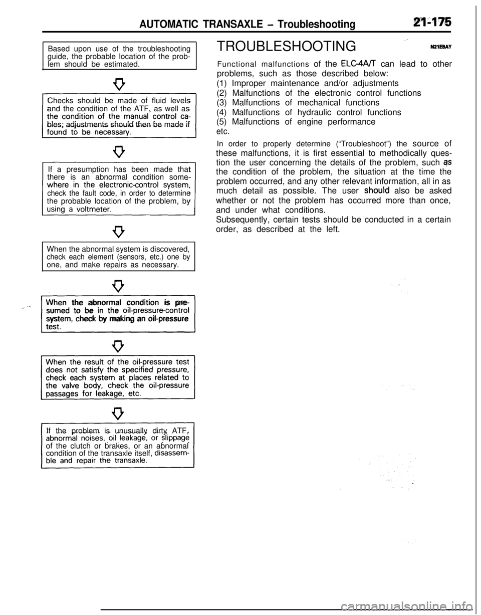
AUTOMATIC TRANSAXLE - TroubleshootingBased upon use of the troubleshooting
guide, the probable location of the prob-
lem should be estimated.
Checks should be made of fluid levels
and the condition of the ATF, as well as
bles; adjustments should then be made if
If a presumption has been made that
there is an abnormal condition some-
check the fault code, in order to determinethe probable location of the problem, by
When the abnormal system is discovered,
check each element (sensors, etc.) one byone, and make repairs as necessary.
“~^II_When the abnormal condition is pre-
sumed to be in the
orI-pressure-controlsystem, check by making an oil-pressure
If the problem is unusually dirty ATF,
of the clutch or brakes, or an abnormal
condition of the transaxle itself,
disassem-TROUBLESHOOTING
”N21EeAYFunctional malfunctions of the ELC4A/T can lead to other
problems, such as those described below:
(1) Improper maintenance and/or adjustments
(2) Malfunctions of the electronic control functions
(3) Malfunctions of mechanical functions
(4) Malfunctions of hydraulic control functions
(5) Malfunctions of engine performance
etc.In order to properly determine (“Troubleshoot”) the source of
these malfunctions, it is first essential to methodically ques-
tion the user concerning the details of the problem, such qs
the condition of the problem, the situation at the time the
problem occurred, and any other relevant information, all in as
much detail as possible. The user
shoutd also be asked
whether or not the problem has occurred more than once,
and under what conditions.
Subsequently, certain tests should be conducted in a certain
order, as described at the left.
Page 903 of 1216

AUTOMATIC TRANSAXLE - service Adjustment Procedures21-209
09Pooi awith this range.
09POOll
TWO382
SERVICE ADJUSTMENT PROCEDURESN21FB6E
TRANSAXLE FLUID LEVEL INSPECTION1. Drive until the fluid temperature reaches the usual tem-
perature
[70-80°C (160- 18O”F)I.2. Place vehicle on level floor.
3. Move selector lever sequentially to every position to fill
torque converter and hydraulic circuit with fluid, then place
lever in “N” Neutral position.
4. Before removing dipstick, wipe all dirt from area around
dipstick. Then take out the dipstick and check the conditionof the fluid.
The transaxle should be overhauled under the following
conditions.l If there is a “burning” odor.
l If the fluid color has become noticeably blacker.
lIf there is a noticeably great amount of metal particles inthe fluid.
5.Check to see if fluid level is in “HOT” range on dipstick. If
fluid level is low, add automatic transaxle fluid until level
reaches “HOT” range.
Transaxle fluid: MOPAR ATF PLUS (Automatic trans-
mission fluid type 7176) or Dia ATF SPor equivalent
Low fluid level can cause a variety of conditions
becaljse it
allows pump to take in air along with fluid. Air trapped in
hydraulic circuit forms bubbles which make fluid spongy.
Therefore, pressures will be erratic, causing delayed shift,
slippy clutch and brakes, etc.
Improper filling can also raise fluid level too high. When
transaxle has too much fluid, gears churn up foam and
cause the same conditions which occur with low fluid level,
resulting in accelerated deterioration of automatic transaxle
fluid.In either case, air bubbles can cause overheating, fluid
oxidation, which can interfere with normal valve, clutch,
and servo operation.Foaming can also result in fluid
escaping from transaxle vent where it may be mistaken for
a leak.6. Be sure to examine fluid on dipstick closely.
TRANSAXLE FLUID REPLACEMENTN21FCBAaRefer to GROUP O-Maintenance Service.
TRANSFER OIL LEVEL INSPECTIONNZlFXAATransfer oil level inspection is the same as for the manual
transaxle transfer.
Refer to GROUP
22-Service Adjustment Procedures.
TRANSFER OIL REPLACEMENTNZlFYAFaTransfer oil replacement is the same as for manual transaxle
transfer.Refer to GROUP
22-Service Adjustment Procedures.
Page 953 of 1216

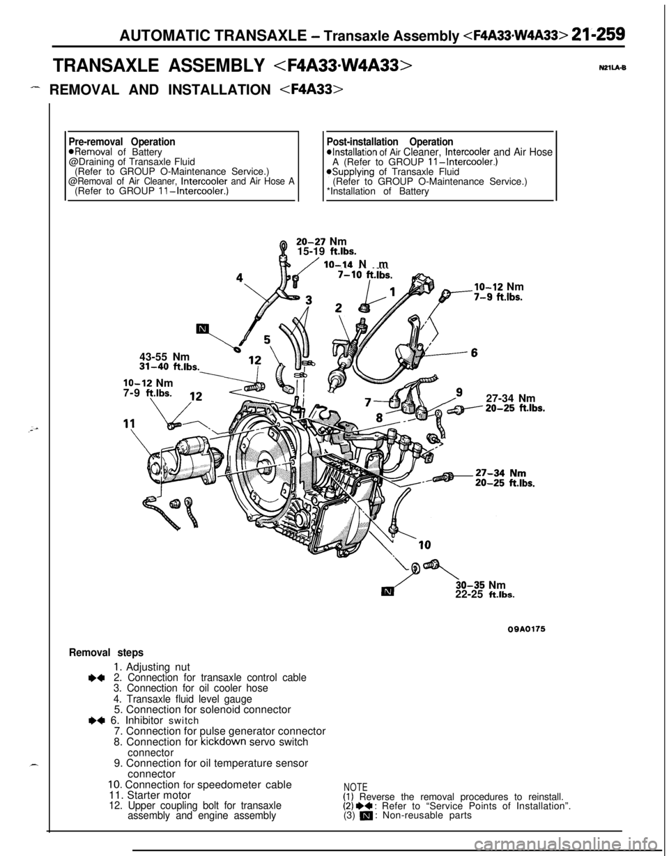
AUTOMATIC TRANSAXLE - Transaxle Assembly
TRANSAXLE ASSEMBLY
- REMOVAL AND INSTALLATION
Pre-removal OperationPost-installation Operation*Removal of Battery*Installation of Air Cleaner, Intercooler and Air Hose@Draining of Transaxle Fluid
A (Refer to GROUP II-Intercooler.)(Refer to GROUP O-Maintenance Service.)
@Removal of Air Cleaner, Intercooler and Air Hose A*Supplying of Transaxle Fluid
(Refer to GROUP O-Maintenance Service.)
(Refer to GROUP II-Intercooler.)*Installation of Battery20-27 Nm
15-19
ft.lbs.
/ IO-14 Nm
43-55 Nm31-40
ft.lbs.
lo-12 Nm
7-9 f?.lbs.
___.Ibs.
lo-12 Nm-7-9 fi.lbs.27-34 Nm20-25
ft.lbs.30-35 Nm
22-25
ft.lbs.
09A0175
Removal steps
1. Adjusting nut+42. Connection for transaxle control cable
3. Connection for oil cooler hose
4. Transaxle fluid level gauge5. Connection for solenoid connector
e+ 6. Inhibitor switch
7. Connection for pulse generator connector
8. Connection for kickdown servo switch
connector9. Connection for oil temperature sensor
connector
10. Connection for speedometer cable
11. Starter motor
12. Upper coupling bolt for transaxle
assembly and engine assembly
NOTE(1) Reverse the removal procedures to reinstall.(2) I)+ : Refer to “Service Points of Installation”.
(3) m : Non-reusable parts
Page 955 of 1216

AUTOMATIC TRANSAXLE - Transaxle Assembly
REMOVAL AND INSTALLATION
(Refer to GROUP
II-Intercooler.)43-55 Nm
\i 513 \20-27 Nm
Q15-19 ft.lbs.
lo-14 NmIO-12 Nm10 ft.lbs.7-9 ftlbs.
/27-34 Nm
ft.lbs.
Y
Es.
Removal steps1. Adjusting nut
l 42. Connection for transaxle control cable3. Connection for oil cooler hose
4. Transaxle fluid level gauge5. Connection for solenoid connector
l +6. Connection for inhibitor switch connector7. Connection for pulse generator connector8. Connection for kickdown servo switch
connector9. Connection for oil temperature sensor
OQAOl63connector
10. Connection for speedometer cable11. Starter motor12. Upper coupling bolt for transaxle
assembly and engine assembly
irkeverse the removal procedures to reinstall.
(2) I)+ : Refer to “Service Points of Installation”
(3) m : Non-reusable parts
Page 960 of 1216

21-266 AUTOMATIC TRANSAXLE -Transaxle Assembly
DISASSEMBLY AND REASSEMBLY
20.Pressure pla?e21.Brake disc22.Brake plate23.Reaction plate
24. Reverse sun gear25. Thrust bearing
#826. Thrust race
#9---
1.Torque converter2.Oil pump assembly3.Gasket4.Thrust washer #I5. Front clutch assembly
6. Thrust race #37. Thrust bearing #48. Thrust washer #227. l-or-ward sun gear
9. Rear clutch assembly28. Planetary carrier assembly
10. Thrust bearing #529.Thrust bearing#I0
11. Rear clutch hub30.Output flange
12. Thrust race
#631. Oil level gauge
13. Thrust bearing #732. Oil filler tube14.Kickdownband33.
Snap ring15.Kickdowndrum34. Kickdown servo switch16.Snap ring35.Snap ring
Ii524
23
TFA0405’36.
Kickdown servo piston
37.Spring
38.Anchor rod
39.Detent assembly40. Manual control shaft
41. Parking roller support
42.Oilpan43.Gasket44. Oil temperature sensor
45.Oil screen
46. Valve body assembly
47. Manual control lever
48.Inhibitor switch49. End clutch shaft50.Bearing retainer51.Thrust bearing #I152. End clutch hub53.Thrust washer
54. End clutch assembly
55.O-ring
56. End clutch cover
57.Pulse generator58:Lock bolt59.Idler shaft60.Idlergear61.Spacer
62.Gasket
Page 962 of 1216

21-268 AUTOMATIC TRANSAXLE -Transaxle Assembly
TFA0409
1.Torque converter2.Oil pump assembly3.Gasket4.Thrust washer #I5.Front clutch assembly
6. Thrust race #37.Thrust bearing #48. Thrust washer
#29.Rear clutch assembly
10. Thrust bearing #511.Rear clutch hub12.Thrust race #613.Thrust bearing #714.Kickdown band15.Kickdown drum16.Snap ring
17.Center support18.Wave spring19.Return spring20.Pressure plate21.Brake disc22.Brake plate23.Reaction plate24.Reverse sun gear25. Thrust bearing #826.Thrust race #927. Forward sun gear
28.Planetary carrier assembly29. Thrust bearing #IO30.Output flange31.Oil level gauge32.Oil filler tube33.Snap ring34.Kickdown servo switch35.
Snap ring36.
Kickdown servo piston
37.Spring38.Anchor rod39.Detent assembly40. Manual control shaft
41. Parking roller support
42.Oilpan43.Gasket44.Oil temperature sensor45.Oil screen46.Valve body assembly47.Manual control lever48.Inhibitor switch49.End clutch shaft50.Bearing retainer51.Thrust bearing #I 1
52. End clutch hub
53.Thrust washer54. End clutch assembly55.O-ring
56. End clutch cover
57.Pulse generator58.Lock bolt59.Idler shaft60.Idler gear61.Spacer
62.Gasket