Page 397 of 1216

ENGINE <2.0L DOHC Engine> - Cylinder Head and Valve9-l 13
.
.
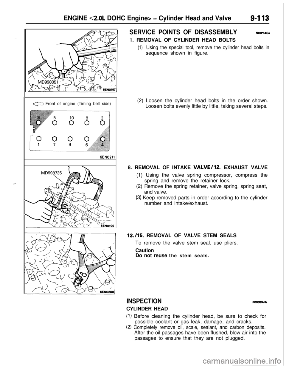
a Front of engine (Timing belt side)
6EN0211
SERVICE POINTS OF DISASSEMBLYNOBPFAti1. REMOVAL OF CYLINDER HEAD BOLTS
(1)Using the special tool, remove the cylinder head bolts insequence shown in figure.
(2) Loosen the cylinder head bolts in the order shown.
Loosen bolts evenly little by little, taking several steps.
8. REMOVAL OF INTAKE
VALVE/12. EXHAUST VALVE
(1) Using the valve spring compressor, compress the
spring and remove the retainer lock.
(2) Remove the spring retainer, valve spring, spring seat,
and valve.
(3) Keep removed parts in order according to the cylinder
number and intake/exhaust.13./15. REMOVAL OF VALVE STEM SEALS
To remove the valve stem seal, use pliers.
Caution
Do not reuse the stem seals.
INSPECTIONCYLINDER HEAD
(1) Before cleaning the cylinder head, be sure to check for
possible coolant or gas leak, damage, and cracks.
(2) Completely remove oil, scale, sealant, and carbon deposits.After the oil passages have been flushed, blow air into the
passages to ensure that they are not plugged.
Page 398 of 1216

9-114ENGINE <2.0L DOHC Engine> - Cylinder Head and Valve
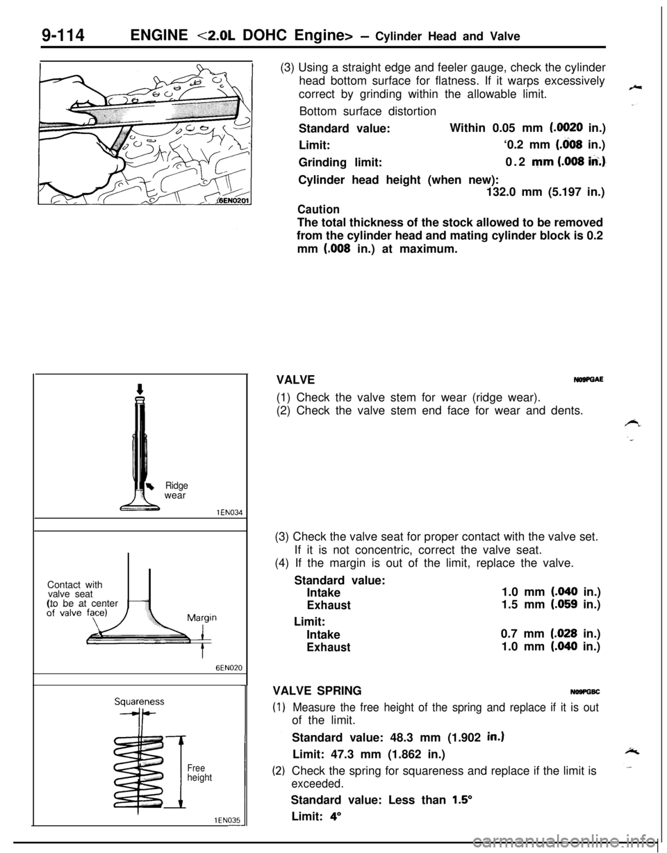
Ridgewear
1 EN034Contact with
valve seat
(to be at center
6EN020
I
Freeheight
1 EN035-(3) Using a straight edge and feeler gauge, check the cylinder
head bottom surface for flatness. If it warps excessively
correct by grinding within the allowable limit.
Bottom surface distortion
Standard value:Within 0.05 mm
(.0020 in.)
Limit:‘0.2 mm
(.dO8 in.)
Grinding limit:0.2 mm
(.008 iA.)-Cylinder head height (when new):
132.0 mm (5.197 in.)
CautionThe total thickness of the stock allowed to be removed
from the cylinder head and mating cylinder block is 0.2
mm
(.008 in.) at maximum.
VALVE
NOSPGAE(1) Check the valve stem for wear (ridge wear).
(2) Check the valve stem end face for wear and dents.
(3) Check the valve seat for proper contact with the valve set.
If it is not concentric, correct the valve seat.
(4) If the margin is out of the limit, replace the valve.
Standard value:
Intake1.0 mm
(.040 in.)
Exhaust1.5 mm (.059 in.)
Limit:
Intake0.7 mm
1.028 in.)
Exhaust1.0 mm (.040 in.)
VALVE SPRING
NOSPGBC
Measure the free height of the spring and replace if it is outof the limit.
Standard value: 48.3 mm (1.902
in.)Limit: 47.3 mm (1.862 in.)
Check the spring for squareness and replace if the limit is
exceeded.Standard value: Less than
1.5’Limit:
4”
Page 399 of 1216

ENGINE <2.0L DOHC Engine> - Cylinder Head and Valve9-115
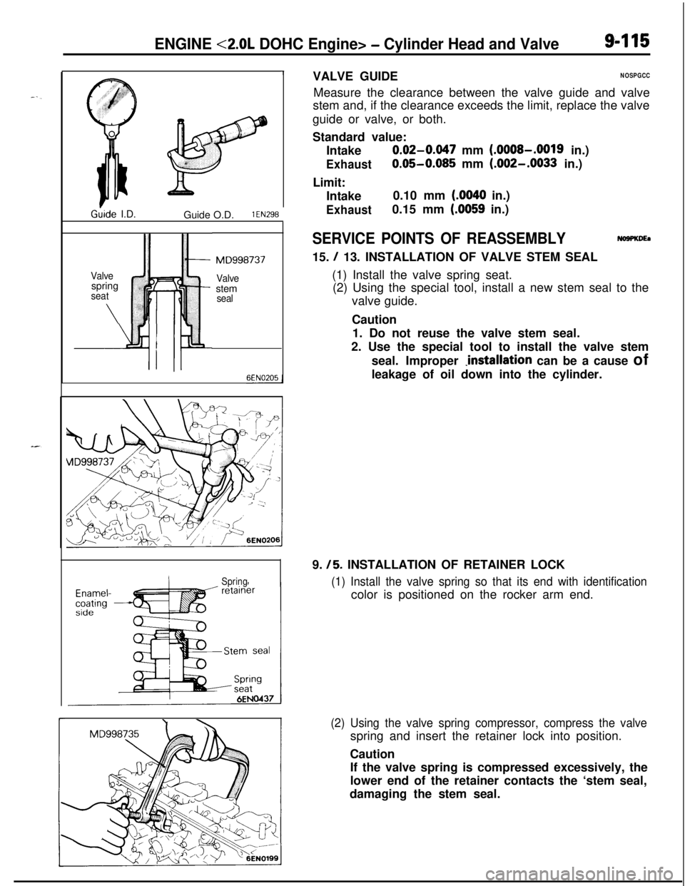
1Ghde I.D.
Guide O.D.
1 EN298
Valve
ispring
*seat
\ Iril
: :
MD998737
Valvestem
seal
SpringVALVE GUIDE
NOSPGCCMeasure the clearance between the valve guide and valve
stem and, if the clearance exceeds the limit, replace the valve
guide or valve, or both.
Standard value:
Intake
0.02-0.047 mm (.OOOS-.0019 in.)
Exhaust0.05-0.085 mm (.002-.0033 in.)
Limit:
Intake0.10 mm
(.0040 in.)
Exhaust0.15 mm (.0059 in.)
SERVICE POINTS OF REASSEMBLYNoaPKDEa15.
/ 13. INSTALLATION OF VALVE STEM SEAL
(1) Install the valve spring seat.
(2) Using the special tool, install a new stem seal to the
valve guide.
Caution
1. Do not reuse the valve stem seal.
2. Use the special tool to install the valve stem
seal. Improper
Jnstallation can be a cause of
leakage of oil down into the cylinder.
9.
/5. INSTALLATION OF RETAINER LOCK
(1) Install the valve spring so that its end with identificationcolor is positioned on the rocker arm end.
(2) Using the valve spring compressor, compress the valvespring and insert the retainer lock into position.
Caution
If the valve spring is compressed excessively, the
lower end of the retainer contacts the ‘stem seal,
damaging the stem seal.
Page 402 of 1216
9-118ENGINE <2.0L DOHC Engine>- Front Case, Oil Pump and Silent Shaft
7LUOOO5
I_ MD998727_ MD998727SERVICE POINTS OF DISASSEMBLY
NOIROA~U6. REMOVAL OF OIL PRESSURE SWITCH
(1) Remove the oil pressure switch terminals.
(2) Using the special tool, remove the oil pressure switch.
CautionSince sealant is coated on the thread area, be
careful not to break it.
9. REMOVAL OF OIL PAN
(1) Remove the all oil pan bolts.
(2) Drive in the special tool between the cylinder block and
oil pan.
NOTE
Never use a screwdriver or chisel, instead of the special
tool, as a deformed oil pan flange will result, resulting inoil leakage.
18. REMOVAL OF PLUG CAP
Using the special tool, remove the plug cap.
20. REMOVAL OF DRIVEN GEAR BOLT
(1) Remove the plug on the side of cylinder block.
(2) Insert a Phillips screwdriver [shank diameter 8 mm
(.32in.)] into the plug hold to block the silent shaft.
(3) Remove the driven gear bolt that secures the oil pump
driven gear to the silent shaft.
Page 403 of 1216

ENGINE <2.0L DOHC Engine>- Front Case, Oil Puma and Silent Shaft9419
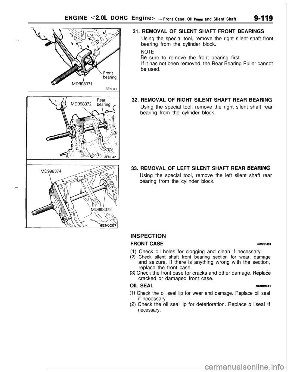
3EN04131. REMOVAL OF SILENT SHAFT FRONT BEARINGS
Using the special tool, remove the right silent shaft front
bearing from the cylinder block.
NOTE
Be sure to remove the front bearing first.
If it has not been removed, the Rear Bearing Puller cannot
be used.
32. REMOVAL OF RIGHT SILENT SHAFT REAR BEARING
Using the special tool, remove the right silent shaft rear
bearing from the cylinder block.
33. REMOVAL OF LEFT SILENT SHAFT REAR
BEARINGUsing the special tool, remove the left silent shaft rear
bearing from the cylinder block.
INSPECTION
FRONT CASE
NOSRCJCl(1) Check oil holes for clogging and clean if necessary.
(2) Check silent shaft front bearing section for wear, damage
and seizure. If there is anything wrong with the section,
replace the front case.
(3) Check the front case for cracks and other damage. Repladecracked or damaged front case.
OIL SEAL
NOSRCMAl
(1) Check the oil seal lip for wear and damage. Replace oil sealif necessary.
(2) Check the oil seal lip for deterioration. Replace oil seal
!if
necessary.
Page 406 of 1216
9-122ENGINE <2.0L DOHC Engine>- Front Case, Oil Pump and Silent ShaftMain gallery
Check valve6LUO14Left
rearbearing
6EN323
SERVICE POINTS OF REASSEMBLYNOSRHAG36. INSTALLATION OF OIL JET
;;;itWhen installing the oil jet, make sure that the nozzle is in
_correct direction, that is, toward the piston.
33. INSTALLATION OF LEFT SILENT SHAFT REAR BEAR-
ING
(1) Install the special (GUIDE PLATE) tool to the cylinder
block.k
(2) Apply engine oil to the rear bearing outer circumference1and bearing hole in cylinder block.
(3) Using the special tool, install the rear bearing.
NOTEThe left rear bearing has no oil holes.
Page 407 of 1216
-
ENGINE <2.0L DOHC Engine>- Front Case, Oil Pump and Silent Shaft
6EN388
6EN390
6EN388
block6EN391
Oil
6FN074
32. INSTALLATION OF RIGHT SILENT SHAFT REAR BEAR-ING
(1) Apply engine oil to outer surface of bearing.
(2) Using special tools, install right rear bearing. Make sure
that oil hole of bearing is aligned with oil hole of cylinder
block.31. INSTALLATION OF SILENT SHAFT FRONT BEARINGS
(1) Using special tools, install front bearing.
(2) Make sure that oil hole of bearing is aligned with oil holeof cylinder block.
Page 409 of 1216
ENGINE <2.0L DOHC Engine> -Front Case, Oil Pump and Silent Shaft9-1256E
N026:(2) Install the front case assembly through a new front
case gasket and temporarily tighten the flange bolts
(other than those for tightening the filter bracket).
(3) Mount the oil filter bracket with oil filter bracket gasket.
Then, install the four bolts with washers.
(4) Tighten the bolts to specification.
NOTE
Bolts indicated by the * symbol should be tightened at atorque of 27-34 Nm
(20-25 ft.1b.s.).20. INSTALLATION OF DRIVEN GEAR BOLT
(1) Insert a Phillips screwdriver into a hole in the left side ofthe cylinder block to lock the silent shaft.
(2) Secure the oil pump driven gear onto the left silent
shaft by tightening the driven gear bolt to specified
torque.18. INSTALLATION OF PLUG CAP
(1) Install a new O-ring to the groove of front case.
(2) Using the special tool, install the plug cap and tighten tospecified torque.