Page 553 of 1216

FUEL SYSTEM -Fuel Pump, Fuel Gauge Unit and Overfill Limiter (Two-Way Valve) p&&g
FUEL PUMP, FUEL GAUGE UNIT AND OVERFILL LIMITER (TWO-WAY
J-.VALVE) REMOVAL AND INSTALLATION
NWJA-Pre-removal Operation
eDraining of the Fuel
Post-installation Operation
l supplying of the Fuel1.4-2.2
ft.lbs.
/ 1.4-2.2ft.lbs.
21-31 Nm
80-100 Nm+
6.5- 10ftlbs.
13AO333
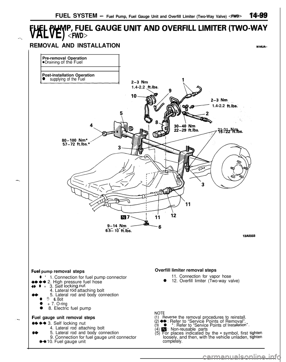
Qel pump removal steps
l *1. Connection for fuel pump connector
C+ ~~ 2. High pressure fuel hoseC+ l +3. Self lockingnut
4. Lateral Pod attaching bolt
a*5. Lateral rod and body connectionl I 6. Boltl + 7. O-ringl 8. Electric fuel pump
Fuel gauge unit removal steps
W e+ 3. Self locking nut
4. Lateral rod attaching bolt
c*5. Lateral rod and body connection9. Connection for fuel gauge unit connector
I)+ 10. Fuel gauge unitOverfill limiter removal steps
11. Connection for vapor hosel 12. Overfill limiter (Two-way valve)
FF:everse the removal procedures to reinstall.(2) +e : Refer to “Service Points of Removal”.(3) l * : Refer to “Service Points of Installation”.(4) m : Non-reusable parts(5) For places indicated by the * symbol, first tightenloosely, and then, with the vehicle unladen, tighten
completely.
Page 554 of 1216

14-100 FUEL SYSTEM- Fuel Pump, Fuel Gauge Unit and Overfill Limiter (Two-Way Valve) 4WD>SERVICE POINTS OF REMOVAL
NI4tmM2. DISCONNECTION OF HIGH PRESSURE FUEL HOSE
Refer to
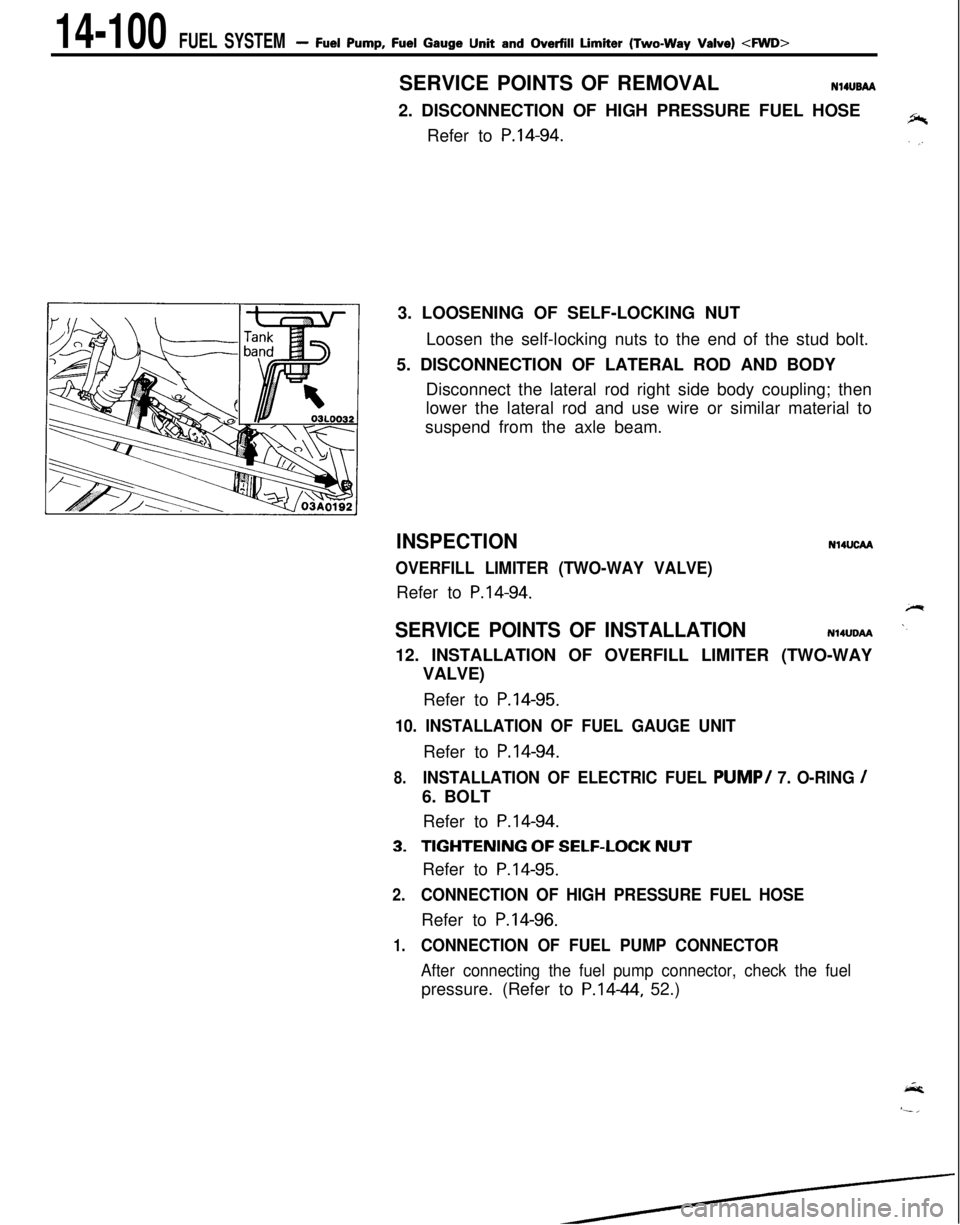
P.14-94.3. LOOSENING OF SELF-LOCKING NUT
Loosen the self-locking nuts to the end of the stud bolt.
5. DISCONNECTION OF LATERAL ROD AND BODY
Disconnect the lateral rod right side body coupling; then
lower the lateral rod and use wire or similar material to
suspend from the axle beam.
INSPECTION
OVERFILL LIMITER (TWO-WAY VALVE)Refer to
P.14-94.
N14UcM
SERVICE POINTS OF INSTALLATIONN14UDAA12. INSTALLATION OF OVERFILL LIMITER (TWO-WAY
VALVE)
Refer to
P.14-95.
10. INSTALLATION OF FUEL GAUGE UNITRefer to
P.14-94.
8.INSTALLATION OF ELECTRIC FUEL PUMP/ 7. O-RING /6. BOLT
Refer to
P.14-94.
3.TIGHTENING OF SELF-LOCK NUTRefer to
P.14-95.
2.CONNECTION OF HIGH PRESSURE FUEL HOSERefer to
P.14-96.
1.CONNECTION OF FUEL PUMP CONNECTOR
After connecting the fuel pump connector, check the fuelpressure. (Refer to P.1444, 52.)
Page 568 of 1216

14-114AUTO-CRUISE CONTROL SYSTEM - Troubleshooting
CHECK CHART
1I. CHECKING THE CONTROL UNIT POWER SUPPLY CIRCUIT
Ignition
switch
I
IAF”7Junction 8
block
tI3
Crurse-controlswitch
OFFDescription of operation
When the cruise control switch (CRUISE) is switched ON whilethe ignition switch is ON, current flows to the ignition switch(IG,), to fuse No.(ll) of the junction block, and to thecruise-control switch (MAIN switch), the control unit, and to
ground.When the ignition switch is turned OFF, the MAIN switch in thecruise control switch is also turned OFF.Troubleshooting hint
ECU terminal voltage
TerminalSignal
No.ConditionsTerminalvoltage
t2Control unitWhen the cruise-System
power supplycontrol switchvoltage
(CRUISE) isswitched ON.
8, 14Control unitAt all timesovground
NOTE+: The connector Nos. in Section “AUTO-CRUISE CONTROL
RELATED HARNESSES” and the connector names in the
junction block are represented.
(Applicable on the next page and subsequence.)13AO3632. CHECKING THE SET SWITCH
Auto-cruisecontrol unitDescription of operation
When the SET switch is switched ON (at the vehicle speed
desired to be maintained, and with the CRUISE switch of the
cruise-control switches ON) that vehicle speed is maintained as
a constanf speed.
Furthermore, the constant speed is gradually reduced (the
“coasting” feature) when the SET switch is pressed and held
while the vehicle is traveling at the previously set constant
speed, and, when the SET switch is released, the vehicle then
maintains that newly set constant speed (the speed at whichthe SET switch was released).
Current flows to the control unit, the cruise control switch
(“SET”), and to ground.Troubleshooting hint
Diagnosis-No. 15 (automatically
cancelled)ECU terminal voltage
1 Terrrnal 1 Signal 1 ConditionsrEl
13AO364
Page 569 of 1216

AUTO-CRUISE CONTROL SYSTEM - Troubleshooting
3. CHECKING THE RESUME SWITCH CIRCUIT.
” ,, . .
Auto-cruisecontrol unit
Cruise-controlswitchDescription of operation
The set speed (before cancellation) resumes when the RE-SUME switch is switched ON, even if the constant-speed
control has been cancelled.That speed will not resume, however, even if the RESUME
switch is switched ON, if the CRUISE switch is switched OFF
and if the vehicle speed decreases to 40 km/h’
(25 mph) or
lower.
In addition, when the RESUME is switched ON and held while
the vehicle is traveling at a constant speed, the vehicle speed
will increase; the speed at which the switch is subsequently
released will become the newly set constant speed.Current flows to the control
unit, the cruise control switch
(RESUME), and to ground.
Troubleshopting hint
Diagnosis-No. 15
(automatica& canceelied)ECU terminal voltage
Tez3!alSignalConditionsTerminalvoltage
18RESUMEWhen the RESUMEOVswitchswitch is,switchedON.
When the RESUME
“o”;:“h IS swrtched;;;;g;
\ ‘)
13AO365,,4. CHECKING THE VEHICLE-SPEED SENSOR CIRCUIT
Auto-cruisecontrol unit
Combination
meter
Junction
block
13A0366Description of operation
The vehicle-speed sensor is installed within the sljeedometer; it
sends to the control unit pulse signals that are proportional to
the rotation speed (i.e., the vehicle speed) of the transaxle’soutput gear.
This vehicle-speed sensor is the reed switch type of sensor; it
generates four pulse signals for each rotation of the speedo-
meter’s driven gear.Troubleshooting hint
Diagnosis-No. 12 (automatically
cancelled)ECU terminal voltage
Move the vehicle
forward slowly.
Page 571 of 1216

i-._AUTO-CRUISE CONTROL SYSTEM
- Troubltyshootf$6. CHECKING THE STOP LIGHT SWITCH CIRCUIT
Sub fusible link @
vacuum
w-vStop light
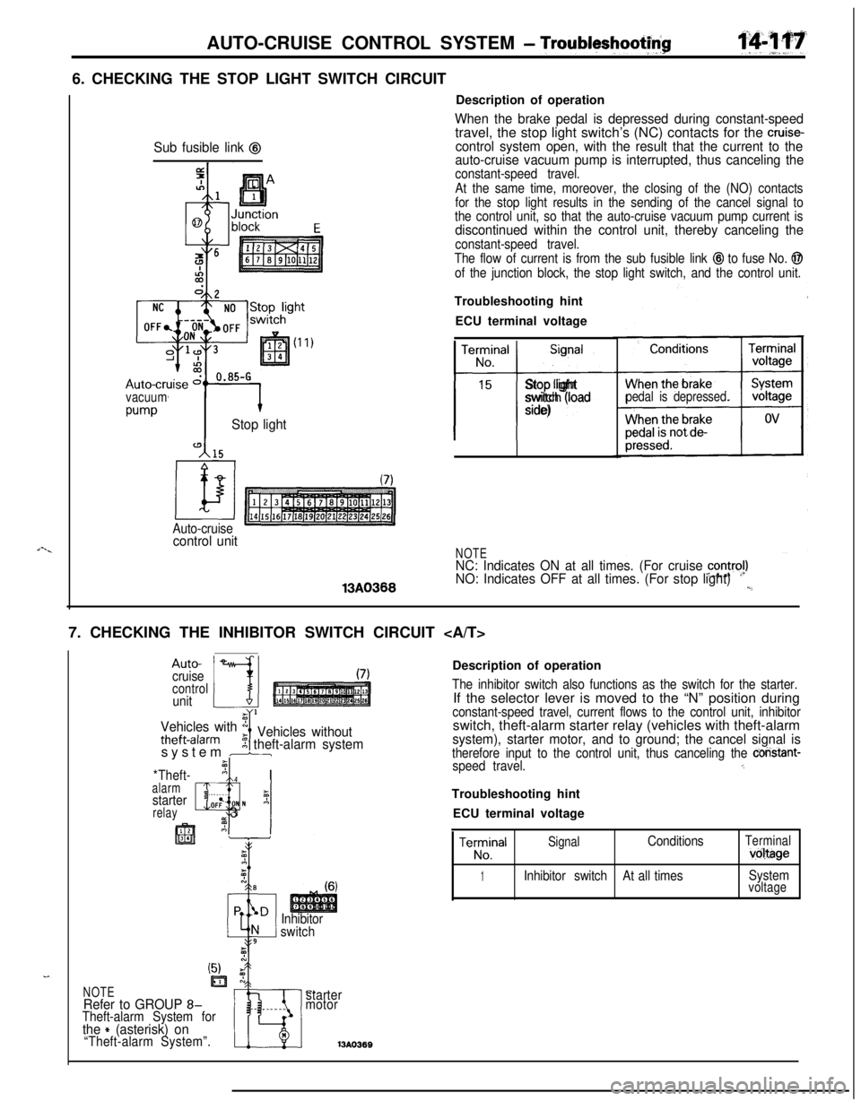
Auto-cruisecontrol unit13A0366Description of operation
When the brake pedal is depressed during constant-speedtravel, the stop light switch’s (NC) contacts for the cruise-control system open, with the result that the current to the
auto-cruise vacuum pump is interrupted, thus canceling the
constant-speed travel.
At the same time, moreover, the closing of the (NO) contacts
for the stop light results in the sending of the cancel signal to
the control unit, so that the auto-cruise vacuum pump current is
discontinued within the control unit, thereby canceling the
constant-speed travel.
The flow of current is from the sub fusible link
@I to fuse No. @
of the junction block, the stop light switch, and the control unit.Troubleshooting hint
ECU terminal voltage
TerminalSignal
No.
15
t-i-
Stop light
switch (load
side)pedal is depressed.
NOTENC: Indicates ON at all times. (For cruise contra!)NO: Indicates OFF at all times. (For stop light)l,_7. CHECKING THE INHIBITOR SWITCH CIRCUIT
Auto-
cruise
controlunit
Vehicles with x
theft-alarmIVehicles without5 theft-alarm systemsystem br
*Theft-’ nI Ialarm, ._I
starterz
relayQlOF: N A_ 3
Inhibitor
switchDescription of operation
The inhibitor switch also functions as the switch for the starter.If the selector lever is moved to the “N” position during
constant-speed travel, current flows to the control unit, inhibitorswitch, theft-alarm starter relay (vehicles with theft-alarm
system), starter motor, and to ground; the cancel signal istherefore input to the control unit, thus canceling the constant-speed travel.5Troubleshooting hint
ECU terminal voltage
TeE!alSignalConditionsTerminalvoltage
1Inhibitor switchAt all timesSystemvoltage
C.starter
motor13A036BNOTERefer to GROUP 8-Theft-alarm System forthe + (asterisk) on“Theft-alarm System”.
Page 572 of 1216
Page 573 of 1216

AUTO-CRUISE CONTROL SYSTEM - Troubleshooting1~~ppGJ”10. CHECKING THE CIRCUITS RELATED TO THE OVERDRIVE-CANCELLATION FUNCTION
block
Ov&rive
Auto-cruisecontrol unitswitch
(16)
A574Al-r
control
unitm
(18)Description of operation
This is a function that cancels the overdrive
fur&on for a
certain fixed period of time, if .during constant-speed travel inoverdrive, the actual vehicle speed decreases to less than the
vehicle speed retained in the memory, and then after a short
time causes the vehicle speed to return to the vehicle speed
retained in the memory.
Overdrive is
cancelled under the following conditions.If, during constant-speed travel, the actual vehicle speed
decreases to 7 km/h (4.4 mph) or more below the set vehicle
speed.
Under either of the conditions described above, the overdrive-
ON signals output from the microcomputer (with the control
unit) are no longer output, and transistor Tr, is switched OFF.
As a result, transistor Tr2 is also switched OFF, causing the
current passing through the overdrive switch of the selector
handle to be interrupted at transistor Tr2, with the result that the
drive is controlled ‘at 3rd gear.Troubleshooting hint
ECU terminal voltage
rerNmdra’SignalConditionsTerminali voltage
104A/T control,
unitWhen the overdrive‘sw$ch IS swrtched$ta;;
11;;tt;iveWhen the overdrives&itch IS switched%‘Gg;
Page 579 of 1216