Page 591 of 1216

AUTO-CRUISE CONTROL SYSTEM - Service Adjustment Procedures
Stopper13A0360
13A0361
2OAO402
lBAOlS2(5) Adjust with adjusting nut A so when link A hits the stopper,
the accelerator cable play (inner cable play) reaches the
standard value.
Standard valueM/T: O-l mm
(O-.04 in.)
A/T: 2-3 mm (.08-.12
in.)(6)
Fix the accelerator cable with the lock nut.
(7) Adjust with adjusting nut
B so when the link B stopper hits
the end of link A, throttle cable play (inner cable play)
reaches the standard value.
Standard value:
l-2 mm (.04-.08 in.)
(8) Fix the throttle cable with lock nut and adjusting bolt
D.‘(9) Adjust with.adjusting nut
C so when the link C stopper hits
the end of link B, the auto-cruise control cable play (inner
cable play) reaches the standard value.
Standard value:
l-2 mm (.04-.08 in.)
(lO)Fix the auto-cruise control cable with the lock nut.
(1 l)After adjusting, confirm that throttle valve fully opens and
closes by operating pedal.
INDIVIDUAL PARTS INSPECTION
AUTO-CRUISE CONTROL SWITCH INSPECTION(1) Remove the knee protector assembly and the lower
column cover.
(2) Disconnect the column switch connector and check the
continuity between the terminals.
O-0: continuity
NeutralRESUME switch ON00
NOTEIf there is an abnormal condition (any condition not described in the
table above), replace the column switch.
Page 594 of 1216
Page 598 of 1216

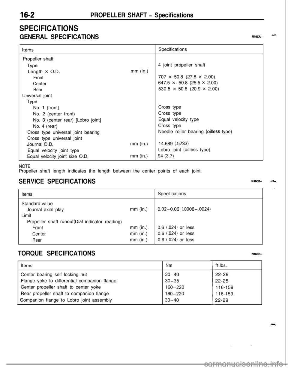
16-2PROPELLER SHAFT - Specifications
SPECIFICATIONS
GENERAL SPECIFICATIONSNWCA--
ItemsPropeller shaft
TypeLength
x O.D.
Front
Center
RearUniversal joint
TypeSpecifications
4 joint propeller shaft
mm (in.)
707
x 50.8 (27.8 x 2.00)
647.5
x. 50.8 (25.5 x 2.00)
530.5
x 50.8 (20.9 x 2.00)
No.
1 (front)
No. 2 (center front)
No. 3 (center rear) [Lobro joint]
No. 4 (rear)
Cross type universal joint bearing
Cross type universal joint
Journal O.D.
Equal velocity joint type
Equal velocity joint size O.D.mm (in.)
mm (in.)Cross type
Cross type
Equal velocity type
Cross type
Needle roller bearing
(oilless type)
14.689
(.5783)Lobro joint
(oilless type)
94 (3.7)
NOTEPropeller shaft length indicates the length between the center points of each joint.
SERVICE SPECIFICATIONSNWCB-
ItemsSpecifications
Standard value
Journal axial playmm (in.)
0.02-0.06 (.0008-.0024)
Limit
Propeller shaft
runout(Dial indicator reading)
Frontmm (in.)
0.6 (.024) or less
Centermm (in.)0.6 (.024) or less
Rearmm (in.)0.6 (.024) or less
TORQUE SPECIFICATIONSNlBCC--
ItemsNmCenter bearing self locking nut
30-40Flange yoke to differential companion flange
30-35Center propeller shaft to center yoke
160-220Rear propeller shaft to companion flange
160-220Companion flange to Lobro joint assembly
30-40tft.lbs.
22-29
22-25
116-159
116-159
22-29
Page 600 of 1216

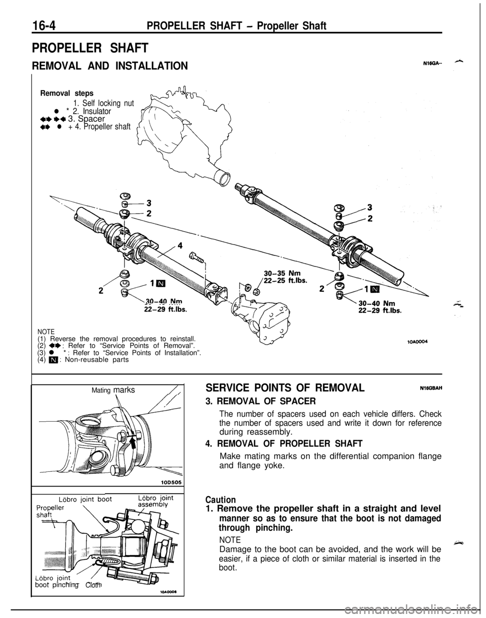
16-4PROPELLER SHAFT - Propeller Shaft
PROPELLER SHAFT
REMOVAL AND INSTALLATIONNlffiA--
Removal steps
1. Self locking nut
l * 2. Insulator*I)+* 3. Spacer+e l + 4. Propeller shaft
- -. - . . .ii-29 ftlbs.
NOTE(1) Reverse the removal procedures to reinstall.
(2)
+* : Refer to “Service Points of Removal”.
(3) l * : Refer to “Service Points of Installation”.
(4) m : Non-reusable parts
lOAOOO4
Mating marks/,
lOD505
LBbro jointboot pinching
Cloth
SERVICE POINTS OF REMOVALNlEGBAH
3. REMOVAL OF SPACER
The number of spacers used on each vehicle differs. Check
the number of spacers used and write it down for referenceduring reassembly.
4. REMOVAL OF PROPELLER SHAFTMake mating marks on the differential companion flange
and flange yoke.
Caution1. Remove the propeller shaft in a straight and level
manner so as to ensure that the boot is not damaged
through pinching.
NOTEDamage to the boot can be avoided, and the work will be
easier, if a piece of cloth or similar material is inserted in the
boot.
Page 601 of 1216

PROPELLER SHAFT - Propeller Shaft
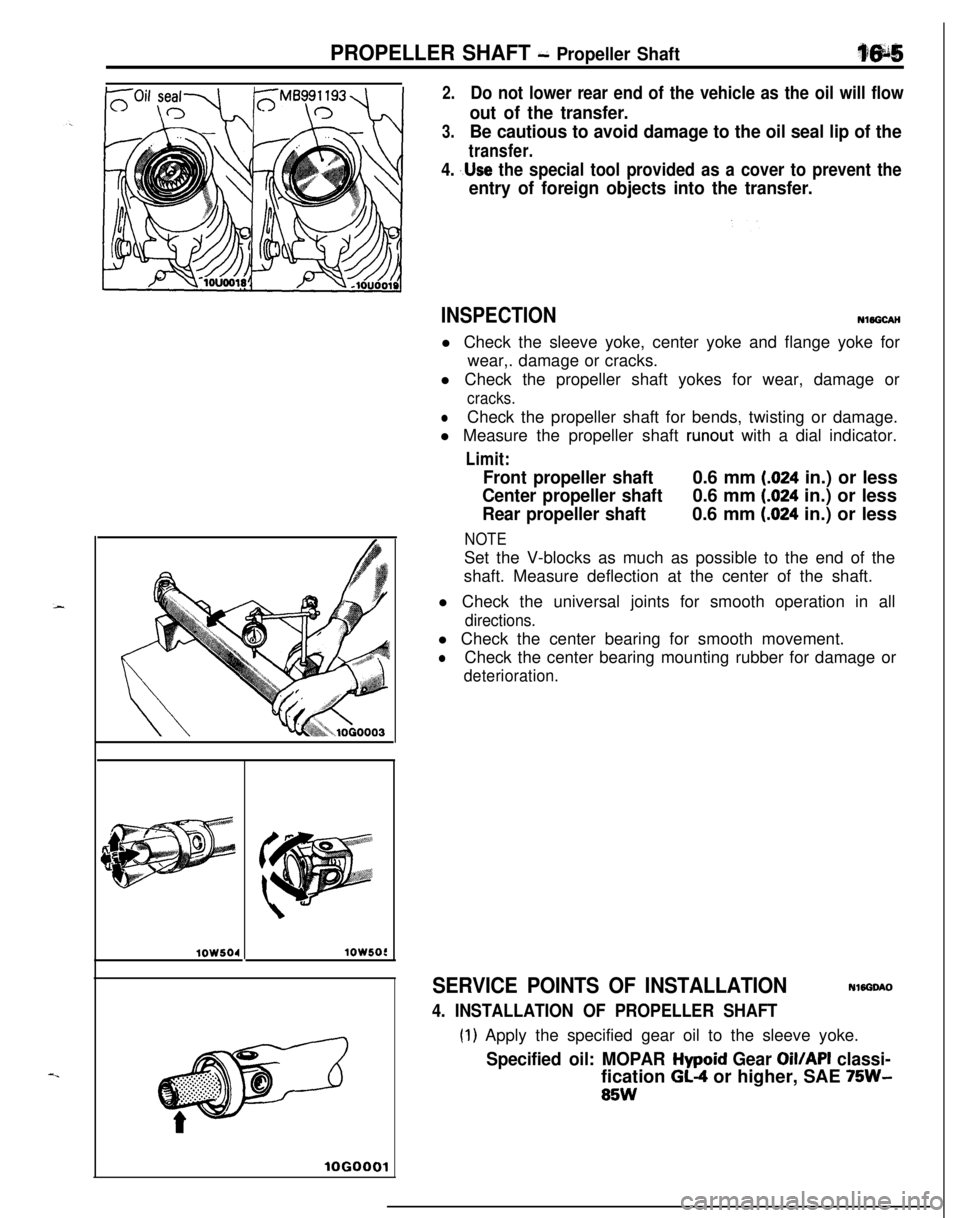
2.Do not lower rear end of the vehicle as the oil will flow
out of the transfer.
3.Be cautious to avoid damage to the oil seal lip of the
transfer.
4. ,.Use the special tool provided as a cover to prevent the
entry of foreign objects into the transfer.
lOW504lOW5OC
lOGO
INSPECTIONNl5GCAH
l Check the sleeve yoke, center yoke and flange yoke for
wear,. damage or cracks.
l Check the propeller shaft yokes for wear, damage or
cracks.
lCheck the propeller shaft for bends, twisting or damage.
l Measure the propeller shaft
runout with a dial indicator.
Limit:
Front propeller shaft0.6 mm (.024 in.) or less
Center propeller shaft0.6 mm (.024 in.) or less
Rear propeller shaft0.6 mm (.024 in.) or less
NOTESet the V-blocks as much as possible to the end of the
shaft. Measure deflection at the center of the shaft.
l Check the universal joints for smooth operation in all
directions.l Check the center bearing for smooth movement.
lCheck the center bearing mounting rubber for damage or
deterioration.
SERVICE POINTS OF INSTALLATIONNWGOAO
4. INSTALLATION OF PROPELLER SHAFT
(1) Apply the specified gear oil to the sleeve yoke.
Specified oil: MOPAR Hypoid Gear Oil/API classi-fication
GL-4 or higher, SAE 75W-
85W
Page 603 of 1216
PROPELLER SHAFT - Propeller Shaft
PROPELLER SHAFT
e-,DISASSEMBLY AND REASSEMBLY
l-
160420 Nm160-&O Nm
116-159
ft.lbs.30-40 Nm
22-29
ft.lbs.
Disassembly stepsl *+*
1. Snap ring+I) l +2. Journal bearing++ 3. Journal
4. Flange yoke5. Sleeve yoke
6. Front propeller shaft41) +47. Lobro joint assembly installation bolt~~ +4 8. Self locking nut4r)+4 9. Center yokea* l + 10. Companion flange~~ 11. Rubber packing++ I)+ 12. Center bearing assembly
13. Rear propeller shaft
l I 14. Snap rjng+* l + 15. Lobro fount assemblyH 16. Rubber packing~~ l + 17. Boot band++ 18. Lobro joint boot~~ 19. Washer20. Center propeller shaft
NOTE(1) Reverse the disassembly procedures to reassemble.(2) ++ : Refer to “Service Points of Disassembly”.(3) l : Refer to “Service Points of Reassembly”.(4) m : Non-reusable parts
Page 604 of 1216

16-8PROPELLER SHAFT - Propeller ShaftlOS511
Journal
M B9908
U\lLijbro joint-Mating marks/assembly
SERVICE POINTS OF DISASSEMBLYNi6SfhK
1. REMOVAL OF SNAP RING
(1) Make mating marks on the yoke and universal joint thatis to be disassembled.
(2) Remove the snap rings from the yoke with snap ring
pliers.
2. REMOVAL OF JOURNAL BEARING
Force out the journal bearings from the yoke with a specialtool by the following procedures.
@ Install the collar to the special tool proper.
@ Press the journal bearing by using the special tool to
force out the journal bearing on the opposite side.
@ Pull out the journal bearing from the yoke.
NOTEIf the journal bearing is hard to remove, strike the yoke
with a plastic hammer.
@IPress the journal shaft by using the special tool to forceout the remaining bearings.
@ Pull out the journal.
7. REMOVAL OF LOBRO JOINT ASSEMBLY INSTALLA-
TION BOLT
(1) Place mating marks on the companion flange and Lobrojoint assembly.
(2) Remove the Lobro joint installation bolts and separate
the Lobro joint from the companion flange.
8. REMOVAL OF SELF LOCKING NUT/S. CENTER YGKE/10. COMPANION
FLANGE/lZ. CENTER BEARING
ASSEMBLY
(1) After placing mating ma,rks on the center yoke and
center propeller shaft, and companion flange and rear
propeller shaft, remove the self locking nuts, then
remove the center yoke and
companjon. flange.
NOTEBe careful not to damage or deform the dust seals on
center propeller shaft assembly and rear propeller shaft.
Page 609 of 1216

PROPELLER SHAFT - Propeller Shaft
NOTEFace the side onto which the center bearing bracket
mating mark is placed and the dust seal is
in,stalled to
the side of the center propeller shaft and
rear.propeller
10X0032
1 OY607
shaft.
11. INSTALLATION OF RUBBER PACKING/lo. COMPAN-
ION FLANGE/S. CENTER YOKE/8. SELF LOCKING NUT
(1) Apply a thin and even coat of the specified grease to therubber packing and fit the packing on the companion
flange.
Specified grease: Repair kit grease(2) Align the mating marks on the center propeller shaft
and center yoke, and the rear propeller shaft and
companion flange, then press fit the center bearing
with self locking nuts, tightening to the specified
torque.
,.
7.INSTALLATION OF LOBRO JOINT ASSEMBLY INSTAL-
LATION BOLTS
(1) Secure the companion flange and Lobro joint assembly
with installation bolts.
(2) Check for grease leakage from the Lobro joint boot andcompanion flange installation parts.
3. JOURNAL/2. JOURNAL BEARING(1) Apply multipurpose grease to the following parts of the
universal joint kit.
@ Shafts and grease sumps of journal
@ Dust seal lips
@ Needle roller bearings
Grease: MOPAR Multi-mileage Lubricant
Part No. 2525035 or equivalent
Caution
Do not apply excessive grease. Otherwise, faulty
fitting of bearing caps and errors in the selection of
snap rings may result.