1991 MITSUBISHI ECLIPSE wheel
[x] Cancel search: wheelPage 237 of 1216

CLUTCH - Clutch Pedal6-7
CLUTCH PEDAL
-. REMOVAL AND INSTALLATIONNOSPA-
.“-Pre-removal Operation
*Removal of the Lap Cooler Duct,Shower Duct (L.H.) and Knee Pro-tector (Refer to GROUP 23%lnstru-ment Panel.)*Removal of the Steering ColumnAssembly (Refer to GROUP 19-Steering Wheel and Shaft.)*Removal of the Relay Box (Indoor)
17-26 Nm
12-19 ft.lbs.
11-17 Nm
8-12 ft.lbs.
IO-15 Nm’ tl(i/\:/ Fl/Yv .1-m.---I- I I KIDS.Post-installation Operation
l installation of the Relay Box (Indoor)l installation of the Steering ColumnAssembly (Refer to GROUP 19-Steering Wheel and Shaft.)l installation of the Lap Cooler Duct,Shower Duct (L.H.) and Knee Pro-tector (Refer to GROUP 23 Instru-ment Panel.)l Adjustment of the Brake Pedal (Re-fer to GROUP 5-Service Adjust-ment Procedures.)aAdjustment of the Clutch Pedal (Re-
fer to P.6-5.)
:k -16
20-25 Nm
14-f8 ft.lbs.
Removal steps
I, Clutch pedal return spring
4. Clutch switch
5. Bolt
7. Clip
l + 8. Bushing
9. Turn over spring
e+ IO. Bushing11. Cotter pinl + 12. Washerl + 13. Clevis pin14. Pedal support bracket assembly
15. Clutch pedal mounting nut
16. Clutch pedal bracket17. Lever
l + 18. Clutch pedal bushing~~ 19. Clutch pedal bushing
20. Pedal rod
e+ 21. Brake pedal bushings
22. Clutch pedal
23. Brake pedal
24. Pedal pad
NOTE(1) Reverse the removal procedures to reinstall.(2) l + : Refer to “Service Points of (3) m : Non-reusable parts
Page 247 of 1216

CLUTCH - Clutch Cover and Disc647
08A0038
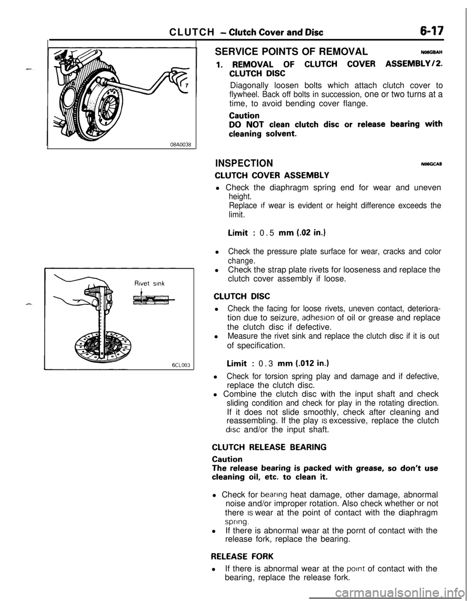
6CLOO3SERVICE POINTS OF REMOVAL
NO6OSAH
1. REMOVAL OF CLUTCH COVER ASSEMBLY/P.
CLUTCH DISCDiagonally loosen bolts which attach clutch cover to
flywheel. Back off bolts in succession, one or two turns at atime, to avoid bending cover flange.
Caution
DO NOT clean clutch disc or release bearing with
cleaning solvent.
INSPECTIONNlNGCAB
CLUTCH COVER ASSEMBLYl Check the diaphragm spring end for wear and uneven
height.
Replace
If wear is evident or height difference exceeds the
limit.Limit
: 0.5 mm (.02 in.)l
Check the pressure plate surface for wear, cracks and color
change.lCheck the strap plate rivets for looseness and replace the
clutch cover assembly if loose.
CLUTCH DISCl
Check the facing for loose rivets, uneven contact, deteriora-tion due to seizure,
adhesron of oil or grease and replace
the clutch disc if defective.
l
Measure the rivet sink and replace the clutch disc if it is outof specification.Limit
: 0.3 mm (.012 in.)l
Check for torsion spring play and damage and if defective,replace the clutch disc.
l Combine the clutch disc with the input shaft and check
sliding condition and check for play in the rotating direction.If it does not slide smoothly, check after cleaning and
reassembling. If the play IS excessive, replace the clutch
drsc and/or the input shaft.
CLUTCH RELEASE BEARING
Caution
The release bearing is packed with grease, so don’t use
cleaning oil, etc. to clean it.l Check for
beanng heat damage, other damage, abnormal
noise and/or improper rotation. Also check whether or not
there IS wear at the point of contact with the diaphragm
spring.lIf there is abnormal wear at the pornt of contact with the
release fork, replace the bearing.
RELEASE FORKlIf there is abnormal wear at the
pornt of contact with the
bearing, replace the release fork.
Page 248 of 1216

6-18CLUTCH - Clutch Cover and Disc
I6CLO33
Clutch disc
T& assemblyClutch cover
6CLO26
SERVICE POINTS OF INSTALLATIONNWGDAT
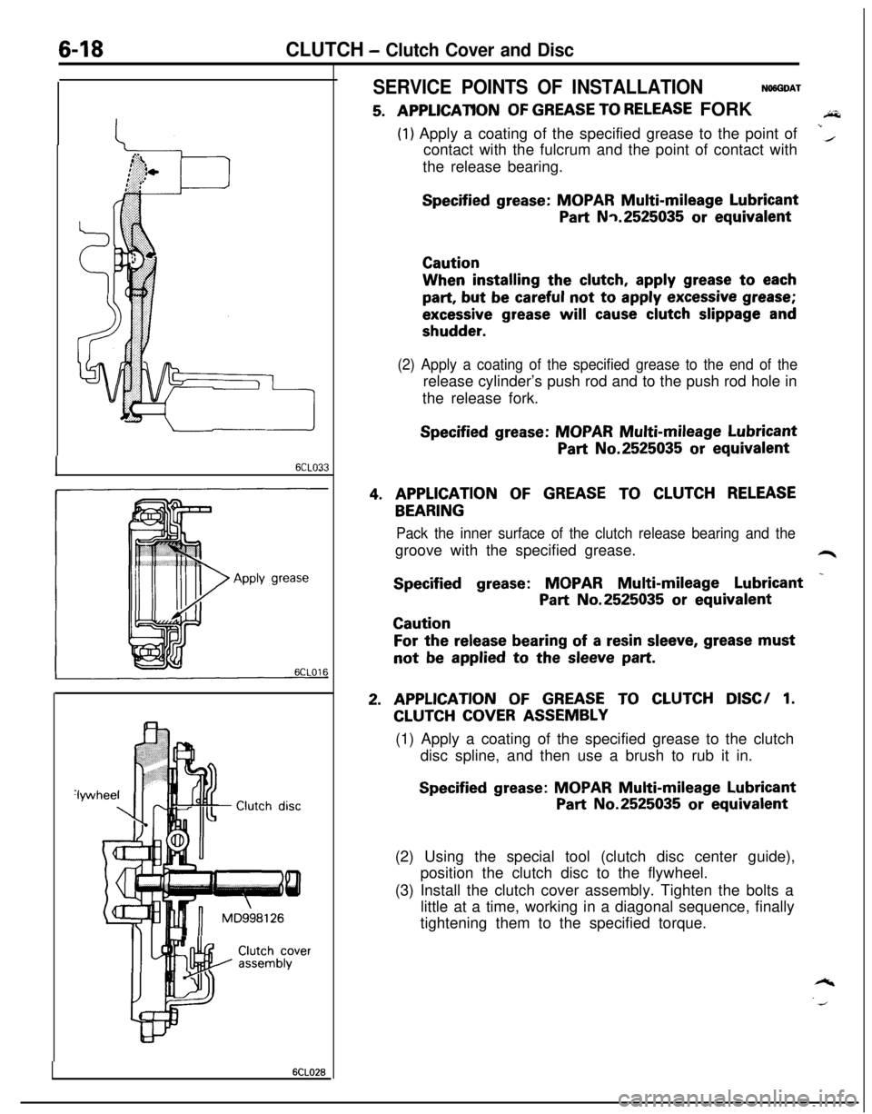
5. A,PPLlCATlONOF GREASE TO RELEASE FORKAi&
(1) Apply a coating of the specified grease to the point of
contact with the fulcrum and the point of contact withi(the release bearing.
Specified grease: MOPAR Multi-mileage Lubricant
Part Nq.2525035 or equivalentCautionWhen installing the
clutch, apply grease to each
part, but be careful not to apply excessive grease;
excessive grease will cause clutch slippage and
shudder.
(2) Apply a coating of the specified grease to the end of therelease cylinder’s push rod and to the push rod hole in
the release fork.
Specified grease: MOPAR Multi-mileage Lubricant
Part No.2525035 or equivalent
4. APPLICATION OF GREASE TO CLUTCH RELEASE
BEARING
Pack the inner surface of the clutch release bearing and thegroove with the specified grease.
L4r
Specified grease: MOPAR Multi-mileage Lubricant _
Part No.2525035 or equivalentCaution
For the release bearing of a resin sleeve, grease mustnot
be applied to the sleeve part.
2. APPLICATION OF GREASE TO CLUTCH DISC/ 1.
CLUTCH COVER ASSEMBLY
(1) Apply a coating of the specified grease to the clutch
disc spline, and then use a brush to rub it in.
Specified grease: MOPAR Multi-mileage Lubricant
Part No.2525035 or equivalent
(2) Using the special tool (clutch disc center guide),
position the clutch disc to the flywheel.
(3) Install the clutch cover assembly. Tighten the bolts a
little at a time, working in a diagonal sequence, finally
tightening them to the specified torque.
Page 285 of 1216

9-1
ENGINE
CONTENTSNOSAA-
ENGINE<1.8L
Engine>..................
24CRANKSHAFT, FLYWHEEL AND
DRIVE PLATE................................................
69
CYLINDER
BLOCK.........................................72
CYLINDERHEADANDVALVE
...................
53CYLINDER HEAD GASKET
...........................
36ENGINE ASSEMBLY
.....................................31ENGINE MOUNTING
....................................
28ENGINE ROLL STOPPER
.............................
30FRONT CASE, OIL PUMP AND
SILENT SHAFT
..............................................
58
OILPANANDOILSCREEN........................34
PISTON AND CONNECTING ROD
..............
65ROCKER ARMS AND ROCKER SHAFTS..
..51ROCKER ARMS, ROCKER ARM SHAFTS
AND CAMSHAFT
..........................................48
SERVICE ADJUSTMENT PROCEDURES..
...24TIMING BELT
................................................41TRANSAXLE MOUNTING
............................
29
ENGINE <2.0L DOHC Engine> . . . . . .
74CAMSHAFTS AND CAMSHAFT
OIL SEALS
. . . . . . . . . . . . . . . . . . . . . . . . . . . . . . . . . . . . . . . . . . . . . . . . . . . . .84CAMSHAFTAND
ROCKERARM. . . . . . . . . . . . . . . .109CRANKSHAFT, FLYWHEEL AND
DRIVE PLATE. . . . . . . . . . . . . . . . . . . . . . . . . . . . . . . . . . . . . . . . . . . . . . . .132
CYLINDERBLOCK. . . . . . . . . . . . . . . . . . . . . . . . . . . . . . . . . . . . . . . . .136
CYLINDERHEADANDVALVE
. . . . . . . . . . . . . . . . . . .112CYLINDER HEAD GASKET
...........................90ENGINE ASSEMBLY
.......................................81ENGINE MOUNTING
......................................77ENGINE ROLL STOPPER
...............................
79FRONT CASE, OIL PUMP AND
SILENT SHAFT
..............................................117OIL PAN AND OIL SCREEN
..........................
87
PISTONANDCONNECTING
ROD..............127SERVICE ADJUSTMENT PROCEDURES..
.....76TIMING BELT
................................................
85TRANSAXLE MOUNTING
............................78
GENERALINFORMATION................2
SPECIAL TOOLS...............................20
SPECIFICATIONS...............................8General Specifications
................................8Sealants and Adhesives
.............................19Service Specifications
.................................8Torque Specifications
.................................18
TROUBLESHOOTING........................23Compression Too Low
Connecting Rod Noise/Main Bearing Noise
Excessive Engine Rolling and Vibration
Noisy Valves
Oil Pressure Drop
Oil Pressure Too High
Timing Belt Noise
Page 296 of 1216

9-12ENGINE - Specifications3msStandard ValueLimit
Undersize rework dimension of pinmm (in.)
0.25
f.010) U.S.44.735-44.750
(1.7612-1.7618)0.50
(.020) U.S.44.485-44.500
(1.7514-1.7520)0.75
(030) U.S.44.235-44.250(1.7415-1.7421)
Undersize rework dimension of journalmm (in.)
0.25
(.OlO) U.S.56.735-56.750(2.2337-2.2342)
0.50
(020) U.S.56.485-56.500(2.2238-2.2244)
0.75
(.030) U.S.56.235-56.250
(2.2140-2.2146)
wheelRunoutmm (in.)Less than 0.13
(0051)I pressure at curb idle speedkPa (psi)80 (11.4) or more
onditions: oil temperature is 75 to
90°C67 to 194”F)l
1 w-wTip clearancemm (in.)
Drive gear
0.06-0.12 (.0024-.0047)0.20 i.0079)Driven gear
0.04-O. 12 (.0016-.0047)0.18 (.0071)Side clearancemm (in.)
Drive gear
0.10-0.16 (.0039-.0063)0.20 (.0079)Driven gear
0.02-0.05 (.0008-.0020)0.15 (.0059)
rlief spring
Free lengthmm (in.)
43.8 (1.724)
Load
[37N at 8.2 Ibs.]mm (in.)
40.1 (1.5787)
ive belt
For alternator
Deflection
mm (in.)
Inspection
9.0- 11.5 (.354-,453)New belt
7.5-9.0 (.295-.354)Used belt
10
i.394)TensionN (Ibs.)
Inspection
250-500 (55- 110)
New belt
500-700 (110-154)Used belt
400 (88)
For air conditioner compressor
Deflectionmm (in.)
Inspection
Approx. 8
(315)New belt
5.0-5.5 (.197-.217)Used belt
6.0-7.0 (.236-.276)
Page 300 of 1216

9-16ENGINE - SpecificationsItems
Connecting rod
Bendmm (in.)
Twistmm (in.)
Connecting rod big end to crankshaft
side clearancemm (in.)
Piston pin press-in loadN (Ibs.)Standard Value
0.05 or less per 100
(0020 or less per 3.937)
0.1 or less per 100
(0040 or less per 3.937)
0.10-0.25 (.0040-.0098)
75,000- 175,000
(1,653-3,858)Limit
0.4
(0157)Connectingrod bearing
Oil clearancemm (in.)
Crankshaft main bearing
Oil clearancemm (in.)
Crankshaft
Pin O.D.mm (in.)
Journal
0.D:mm (in.)
Out-of-roundness of journal and pinmm (in.)
Taper of journal and pinmm (in.)
End playmm (in.)
FlywheelRunoutmm (in.)
Oil pressure at curb idle speedkPa (psi)
[Conditions: oil temperature is 75 to
90°C(167 to 194”F)l
0.02-0.05 (.0008-.0020)
0.02-0.05 (.0008-.0020)
44.980-44.995
(1.7709-1.7715)
56.980-56.995
(2.2433-2.2439)Less than
0.015 (.0006)Less than
0.005 (.0002)
0.05-0.18 (.0020-.0070)80
(11.4) or more0.1
(.004)0.1
(004)0.25
LOO981Less than 0.13
(.0051)Oil pump
Tip clearancemm (in.)
Drive gear
0.16-0.21 (.0063-.0083)0.25 f.0098)Driven gear
0.13-0.18 (.0051-.0071)0.25 t.0098)Side clearancemm (in.)
Drive gear
0.08-0.14 (.0031-.0055)0.25 (.0098)Driven gear
0.06-0.12 (.0024-.0047)0.25 i.0098)
qelief spring
Free lengthmm (in.)
46.6 (1.835)
Load
[61N at 13.4 Ibs.]mm (in.)
40.1 (1.579)
Page 302 of 1216

9-18ENGINE - Specifications
TORQUE SPECIFICATIONS
NO9CG-Items
Engine mount insulator nut (large)
(small)
Engine mount bracket nut or bolt
Transaxle mount insulator nut
Transaxle mount to body
Front roll stopper insulator nut
Front roll stopper bracket to centermember
Rear roll stopper insulator nut
Rear roll stopper bracket to centermember
Accelerator cable adjusting bolts
Fuel high pressure hose to delivery pipe
Ground cable to air intake manifold
Control wiring harness to air intake plenum
Power steering oil pump to bracket
Air conditioner to bracketcompressor
Exhaust pipe clamp bolt
Exhaust pipe to rubber hanger
Oil drain plug
panOil (bolts)
pan(nuts)VVater pulley
pump
Tensioner pulley bracket (air conditioner compressor)
Timing belt front coverCrankshaft sprocket
Camshaft sprocket
Timing belt “B” tensioner bolt
-eft engine support bracket3il switch
pressure3il unit
pressure gauge
Iii filter bracket
Iii cover
pumpqelief plug
‘lywheel or drive plate
ixhaust pipe bracket
support
‘rant roll stopper bracket
Iear roll stopper bracket‘rant engine bracket
support
:1.8L Engine>
Oil screen
Rocker cover
Camshaft bearing cap bolt (6 x 20)
(8 x 65)
Exhaust pipe to exhaust manifold
Intake manifold bolt
stay
Cylinder head bolt
Crankshaft pulley
Crankshaft damper pulleyNm
ftlbs.
60-8043-58
30-4022-29
50-6536-47
60-8043-58
40-5029-36
50-6536-47
40-5029-36
40-5029-36
40-5029-36
4-63-4
4-6
3-4
4-6
3-4
4-6
3-4
35-45
25-33
23-27
17-20
30-4022-29
10-157-l 135-45
25-33
6-84-6
5-73.5-5
8-106-7
23-27
17-20
10-127-9
110-13080-94
80-10058-72
15-2211-16
30-4222-308-126-9
8-126-9
15-2211-16
15-1811-13
40-5029-36
130-14094-101
30-4222-3055-75
40-54
110-13080-94
50-7036-51
18-2513-18
5-74-5
20-2714-2019-21
14-15
30-4022-29
18-2513-18
70-7551-5415-1811-13
15-1811-13
Page 309 of 1216

ENGINE <1.8L Engine>- Service Adjustment Procedures9-25
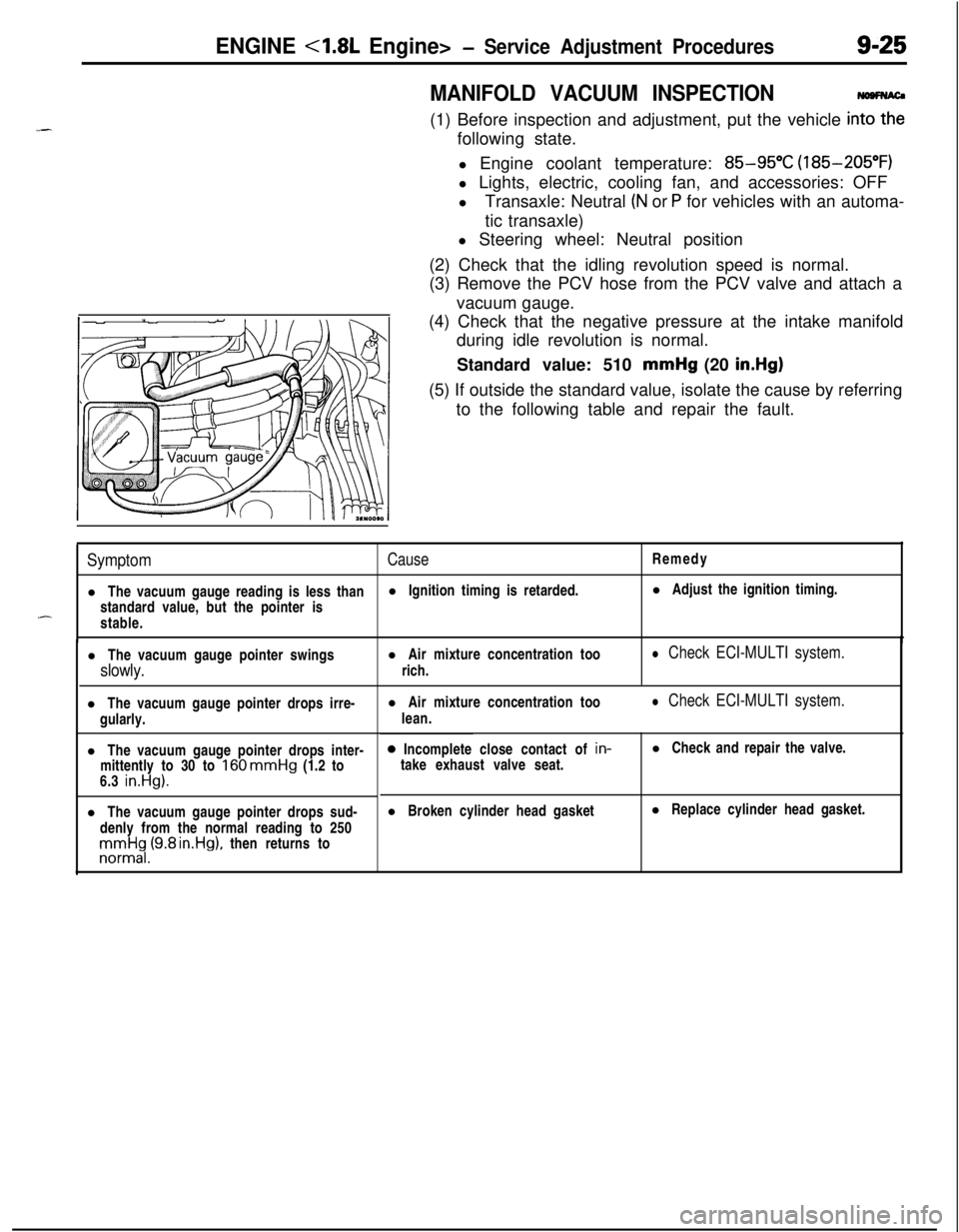
MANIFOLD VACUUM INSPECTION(1) Before inspection and adjustment, put the vehicle
in=following state.
l Engine coolant temperature:
85-95°C (185-205°F)
l Lights, electric, cooling fan, and accessories: OFF
lTransaxle: Neutral
(N or P for vehicles with an automa-
tic transaxle)
l Steering wheel: Neutral position
(2) Check that the idling revolution speed is normal.
(3) Remove the PCV hose from the PCV valve and attach a
vacuum gauge.
(4) Check that the negative pressure at the intake manifold
during idle revolution is normal.
Standard value: 510 mmHg (20
in.Hg)(5) If outside the standard value, isolate the cause by referring
to the following table and repair the fault.
SymptomCauseRemedy
l The vacuum gauge reading is less thanl Ignition timing is retarded.l Adjust the ignition timing.
standard value, but the pointer is
-stable.
l The vacuum gauge pointer swingsl Air mixture concentration too
slowly.rich.
l Check ECI-MULTI system.l The vacuum gauge pointer drops irre-
gularly.
l The vacuum gauge pointer drops inter-
mittently to 30 to
160 mmHg (1.2 to
6.3 in.Hg).l The vacuum gauge pointer drops sud-
denly from the normal reading to 250rronnrt$,(9.8 rn.Hg), then returns tol Air mixture concentration too
lean.
l Check ECI-MULTI system.0 Incomplete close contact of in-
take exhaust valve seat.l Check and repair the valve.
l Broken cylinder head gasketl Replace cylinder head gasket.