Page 310 of 1216

9-26ENGINE <1.8L Engine> -Service Adjustment Procedures
TIMING BELT TENSION ADJUSTMENTNOSFGBCThere are two access holes provided in the timing belt front
lower cover. The two access holes can be used to readjust thetension of the timing belt, by following the procedures
described below, without the necessity of removing the timing
belt front lower cover. Note, however, that timing belt “B”,
which drives the right silent shaft, cannot be adjusted unless
the cover is removed.
(1) Turn the steering wheel all the way to the left.
(2) Remove the left side undercover panel.
NOTEThis work is done so that the crankshaft can be turned.
(3) Place a piece of wood against the engine oil pan and jack
(4)
:tmove the engine mounting bracket.
(5) Remove the timging belt front upper cover.
(6) Remove the four spark plugs.
(7) Turn the crankshaft clockwise and check the timing belt
condition.
OlAOOBlTiming mark
(on upper under cover)
Timing mark
(on camshaft sprocket)
OlR0153cover
‘I!i
OlA0082
01 A0083(8) Turn the crankshaft clockwise and align the timing marks.
(9) Remove the air conditioner drive belt and the alternator
drive belt.
(10)Remove the access cover (two places). There are easily
removed by inserting a screwdriver into the slots indicated
by the raised arrows in the timing belt cover and twisting.
(1l)lnser-t a socket wrench [a 14 mm (.55 in.) box wrench]
through the hole in the access cover and loosen the timing
belt tension bolt and nut.
Caution
The timing belt tension bolt and nut need only be
loosened
180”-200”. Any further loosening might re-
sult in their falling off inside the timing belt cover.
Page 353 of 1216

ENGINE <1.8L Engine> -Crankshaft, Flywheel and Drive PlateS-69
CRANKSHAFT, FLYWHEEL AND DRIVE PLATE
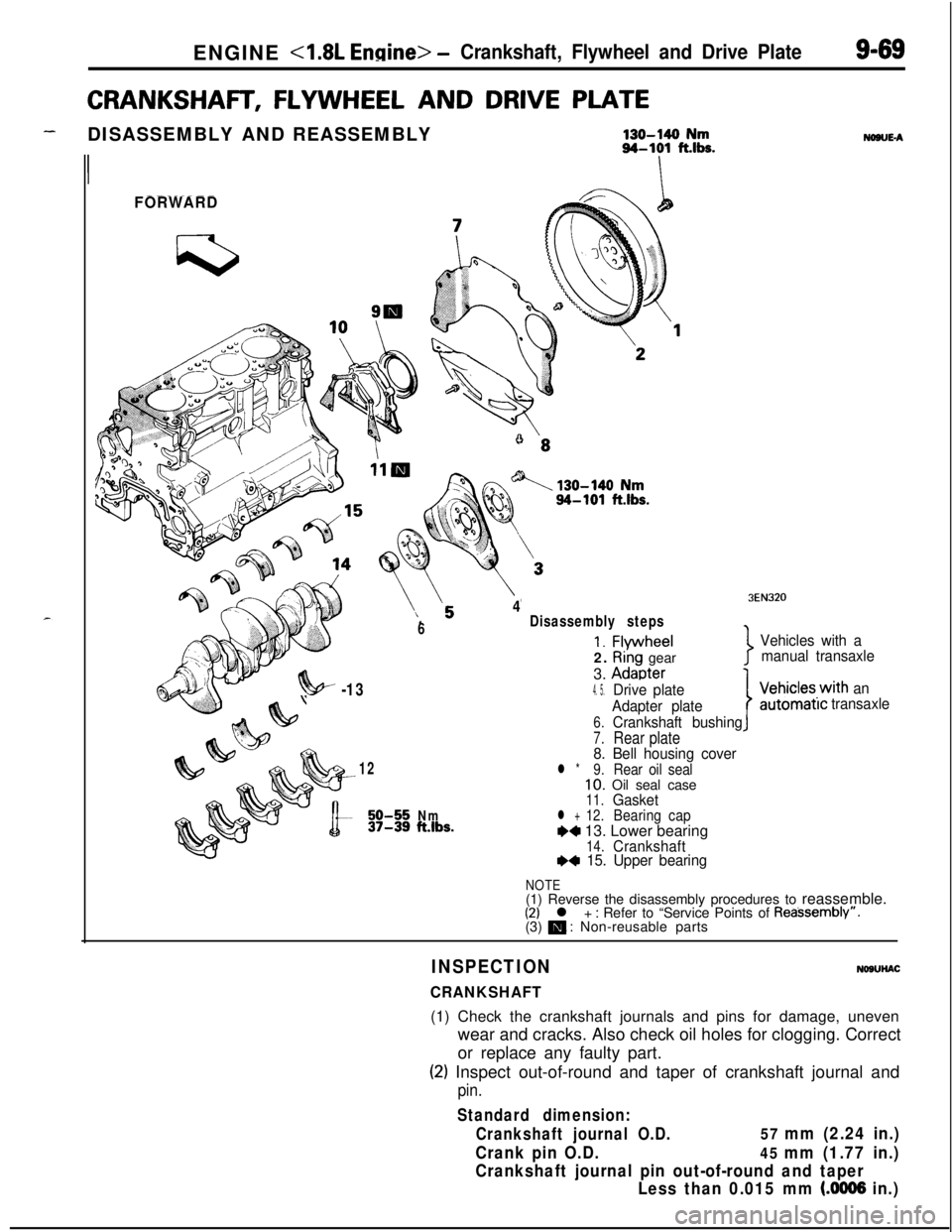
-DISASSEMBLY AND REASSEMBLY130-140 Nm94-101 fths.
II
FORWARD
6
4Disassembly steps
1. Flvwheel2.
Ri’ng gear
3.
Adaoter
NONE-A
3EN320
Vehicles with a
manual transaxle
7
?!w -134. 5.Drive plate
Adapter plate
6.Crankshaft bushing
7.Rear plate8. Bell housing cover12l *9.Rear oil seal10. Oil seal case11.Gasket50-55Nm12.37-39ft.lbs.l +BearingcapW 13. Lower bearing14.CrankshaftI)* 15. Upper bearing
IVehicles.with an
automatrctransaxle
NOTE(1) Reverse the disassembly procedures to reassemble.
(2) l + : Refer to “Service Points of Reassembly”.
(3) m : Non-reusable parts
INSPECTION
CRANKSHAFT
NOSUHAC(1) Check the crankshaft journals and pins for damage, uneven
wear and cracks. Also check oil holes for clogging. Correct
or replace any faulty part.
(2) Inspect out-of-round and taper of crankshaft journal and
pin.
Standard dimension:
Crankshaft journal O.D.
57 mm (2.24 in.)
Crank pin O.D.
45 mm (1.77 in.)
Crankshaft journal pin out-of-round and taper
Less than 0.015 mm
(.0006 in.)
Page 354 of 1216

ENGINE <1.8L Engine> -Crankshaft, Flywheel and Drive Plate
3EN055
6EN043
1 EN067
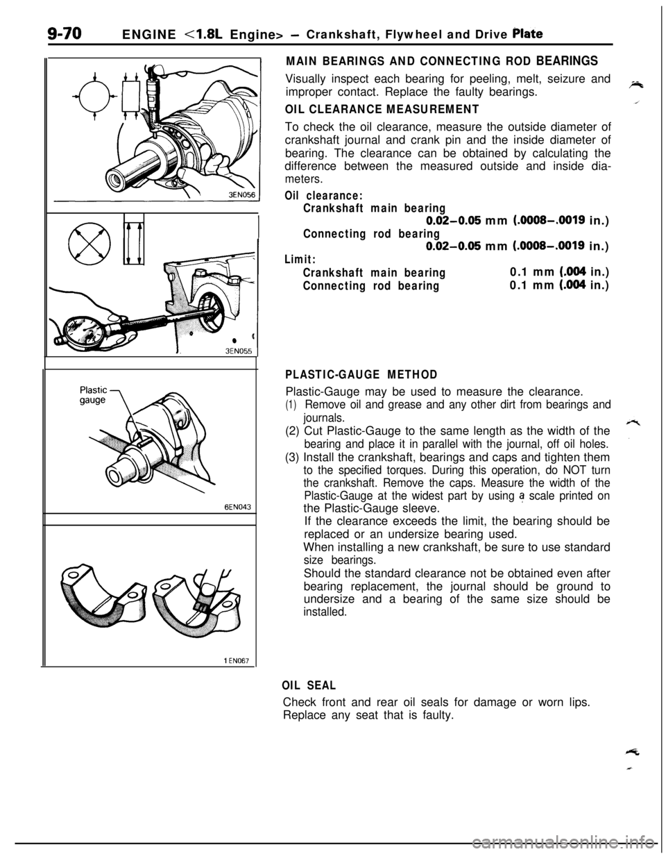
MAIN BEARINGS AND CONNECTING ROD BEARINGSVisually inspect each bearing for peeling, melt, seizure and
improper contact. Replace the faulty bearings.
OIL CLEARANCE MEASUREMENTTo check the oil clearance, measure the outside diameter of
crankshaft journal and crank pin and the inside diameter of
bearing. The clearance can be obtained by calculating the
difference between the measured outside and inside dia-
meters.
Oil clearance:
Crankshaft main bearing
0.02-0.05 mm (.OOOS-.0019 in.)
Connecting rod bearing
0.02-0.05 mm (.OOOS-.0019 in.)
Limit:
Crankshaft main bearing0.1 mm (.004 in.)
Connecting rod bearing0.1 mm (.004 in.)
PLASTIC-GAUGE METHODPlastic-Gauge may be used to measure the clearance.
(1)Remove oil and grease and any other dirt from bearings and
journals.(2) Cut Plastic-Gauge to the same length as the width of the
bearing and place it in parallel with the journal, off oil holes.(3) Install the crankshaft, bearings and caps and tighten them
to the specified torques. During this operation, do NOT turn
the crankshaft. Remove the caps. Measure the width of the
Plastic-Gauge at the widest part by using
a scale printed onthe Plastic-Gauge sleeve.
If the clearance exceeds the limit, the bearing should be
replaced or an undersize bearing used.
When installing a new crankshaft, be sure to use standard
size bearings.Should the standard clearance not be obtained even after
bearing replacement, the journal should be ground to
undersize and a bearing of the same size should be
installed.
OIL SEALCheck front and rear oil seals for damage or worn lips.
Replace any seat that is faulty.
Page 355 of 1216

ENGINE - Crankshaft, Flwvheel and Drive Plate9-71
3EN30’lrrow mark toward
cap No,
I
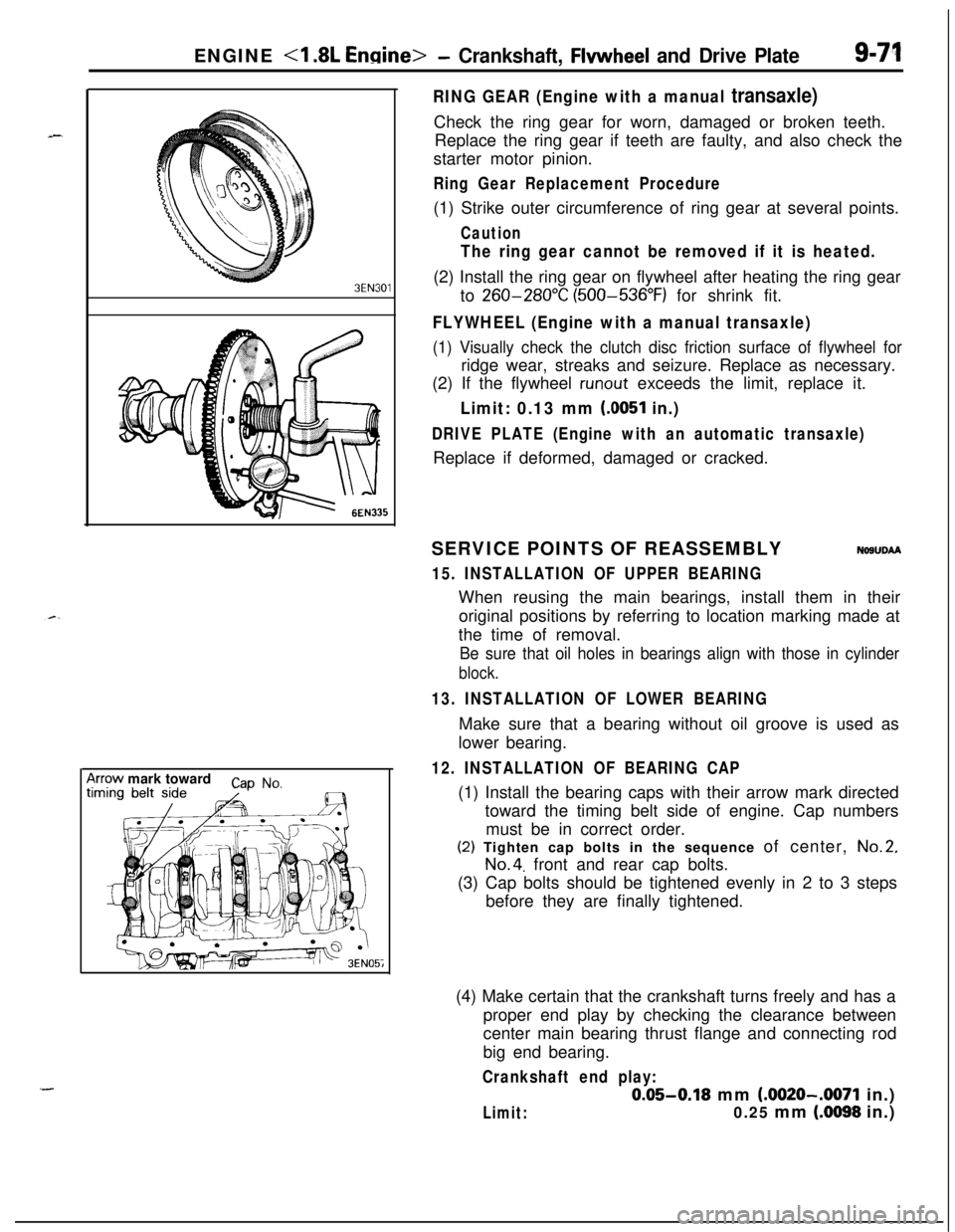
RING GEAR (Engine with a manual transaxle)Check the ring gear for worn, damaged or broken teeth.
Replace the ring gear if teeth are faulty, and also check the
starter motor pinion.
Ring Gear Replacement Procedure(1) Strike outer circumference of ring gear at several points.
Caution
The ring gear cannot be removed if it is heated.(2) Install the ring gear on flywheel after heating the ring gear
to
260-280°C (500-536°F) for shrink fit.
FLYWHEEL (Engine with a manual transaxle)
(1) Visually check the clutch disc friction surface of flywheel forridge wear, streaks and seizure. Replace as necessary.
(2) If the flywheel
runout exceeds the limit, replace it.
Limit: 0.13 mm (0051 in.)
DRIVE PLATE (Engine with an automatic transaxle)Replace if deformed, damaged or cracked.
SERVICE POINTS OF REASSEMBLY
NOSUDAA
15. INSTALLATION OF UPPER BEARINGWhen reusing the main bearings, install them in their
original positions by referring to location marking made at
the time of removal.
Be sure that oil holes in bearings align with those in cylinder
block.
13. INSTALLATION OF LOWER BEARINGMake sure that a bearing without oil groove is used as
lower bearing.
12. INSTALLATION OF BEARING CAP(1) Install the bearing caps with their arrow mark directed
toward the timing belt side of engine. Cap numbers
must be in correct order.(2) Tighten cap bolts in the sequence of center,
No.2,
No.4. front and rear cap bolts.
(3) Cap bolts should be tightened evenly in 2 to 3 steps
before they are finally tightened.
(4) Make certain that the crankshaft turns freely and has a
proper end play by checking the clearance between
center main bearing thrust flange and connecting rod
big end bearing.
Crankshaft end play:
0.05-0.18 mm (.0020-.0071 in.)
Limit:0.25 mm (.0098 in.)
Page 356 of 1216

9-72ENGINE <1.8L Engine> -Crankshaft, Flywheel and Drive Plate/Cylinder Block
PressOil seal
I
MD99801 1
/
Oil seal case1 EN06L
CYLINDER BLOCK
i//
199.
INSTALLATlON OF REAR OIL SEAL
Install oil seal in the crankshaft rear oil seal case. Using the
special tool, press fit the oil seal all the way in without tiltingiii
it.DISASSEMBLY AND REASSEMBLY
FORWARD
50-70 Nm37-50 ft.lbs.
30-42 Nm22-30 ft.lbs.
NDBVF-A
110-130 Nm80-94 ft.lbs.1. Exhaust pipe support bracket
2. Front roll stopper bracket
3. Rear roll stopper bracket
4. Left engine support bracket5. Cylinder block6. Engine mount bracket
3EN0092
INSPECTIONl Visually check the cylinder block for scores, rust and
corrosion. Also check for cracks or any other faults by using
the magnaflux method. Correct or replace the block if
faulty.
lMeasure the cylinder bore with a cylinder gauge at three
levels and in two directions A and
B as shown. If
out-of-round or taper is more than specified or if the
cylinder walls are badly scuffed or scored, the cylinder
&block should be rebored and honed, and new oversize
_pistons and rings fitted.
Measuring points are as shown.
Cylinder bore: 80.8 mm (3.173 in.)
Out-of-round and taper: 0.01 mm (.0004 in.)
Page 359 of 1216

_-
a--ENGINE
<2.0L DOHC Engine> -Service Adjustment Procedures9-75
JMANIFOLD VACUUM INSPECTION
NO9FNAO(1) Before inspection and adjustment, put the vehicle into the
following state.
l Engine coolant temperature:
85-g5”C (185-205°F)
l Lights, electric, cooling fan, and accessories: OFF
lTransaxle: Neutral (N or
P for vehicles with an automa-
tic transaxle)
l Steering wheel: Neutral position
(2) Check that the idling revolution speed is normal.
(3) Remove the PCV hose from the PCV valve and attach a
vacuum gauge.
(4) Check that the negative pressure at the intake manifold
during idle revolution is normal.
Standard value:: 490
mmHg (19.3 in.Hg): 480
mmHg (18.9 in.Hg)(5) If outside the standard value, isolate the cause by referring
to the following table and repair the fault.
ymptomICause1 Remedy
The vacuum gauge reading is less than
standard value, but the pointer is
stable.
The vacuum gauge pointer swingsslowly.
l Ignition timing is retarded.
l Air mixture concentration too
rich.
l Adjust the ignition timing.
l Check ECI-MULTI system.
The vacuum gauge pointer drops
irre-gularly.l Air mixture concentration too
lean.
l Check ECI-MULTI system.
The vacuum gauge pointer drops inter-mittently to 30 to 160
mmHg (1.2 to
6.3 in.Hg).
The vacuum gauge pointer drops sud-
denly from the normal reading to 250
mmHg (9.8 in.Hg), then returns tonormal.
l Incomplete close contact of in-
take and exhaust valve seat.
l Broken cylinder head gasket
l Check and repair the valve.
l Replace cylinder head gasket.
Page 416 of 1216
g-132 ENGINE <2.0L DOHC ‘Engine>- Crankshaft, Flywheel and Drive Plate
CRANKSHAFT, FLYWHEEL AND DRIVE PLATEDISASSEMBLY AND REASSEMBLY
NOBUE-B
1
lo-12 Nm5
7-9 ft.lbs.I
FORWARDIO-12
N/m7-9 ft.lbs.
130-140 Nm94-101 ft.lbs.
I47-51
ftlbs.
130-140 Nm‘94-101 ft.lbs.
6ENO227
Disassembly steps
1. Flywheel (Manual transaxle)
2. Adapter plate3. Drive plateAutomatic
4. Crankshaft bushingtransaxle
5. Rear plate6. Bell housing cover
7. Oil seal case8. Gasket
l + 9. Oil separatorl a 10. Oil seall + 11. Bearing cap
l + 12. Lower bearing
13. Crankshaftl + 14. Upper bearing
NOTE(1) Reverse the disassembly procedures to reassemble.(2) e+ : Refer to “Service Points of Reassembly”.(3) 0 : Non-reusable parts
Page 417 of 1216

ENGINE <2.0L DOHC Engine>- Crankshaft, Flywheel and Drive Plate,91133
INSPECTIONNOSUHAD
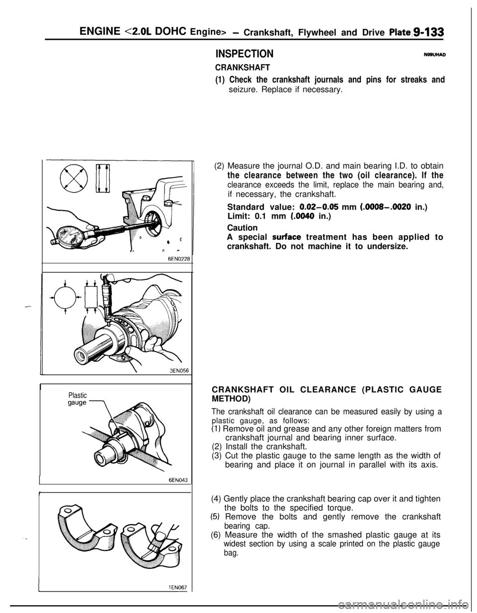
CRANKSHAFT(1) Check the crankshaft journals and pins for streaks and
seizure. Replace if necessary.
6EN0’228
\3EN056
Plastic
6EN043
. .
I1 EN067-(2) Measure the journal O.D. and main bearing I.D. to obtain
the clearance between the two (oil clearance). If the
clearance exceeds the limit, replace the main bearing and,if necessary, the crankshaft.
Standard value:
0.02-0.05 mm (.OOOS-.0020 in.)
Limit: 0.1 mm
(.0040 in.)
Caution
A special
surface treatment has been applied to
crankshaft. Do not machine it to undersize.
CRANKSHAFT OIL CLEARANCE (PLASTIC GAUGE
METHOD)
The crankshaft oil clearance can be measured easily by using aplastic gauge, as follows:
(1) Remove oil and grease and any other foreign matters from
crankshaft journal and bearing inner surface.
(2) Install the crankshaft.
(3) Cut the plastic gauge to the same length as the width of
bearing and place it on journal in parallel with its axis.
(4) Gently place the crankshaft bearing cap over it and tighten
the bolts to the specified torque.
(5) Remove the bolts and gently remove the crankshaft
bearing cap.(6) Measure the width of the smashed plastic gauge at its
widest section by using a scale printed on the plastic gauge
bag.