1991 MITSUBISHI ECLIPSE wheel
[x] Cancel search: wheelPage 418 of 1216

g-134 ENGINE <2.0L DOHC Engine>- Crankshaft, Flywheel and Drive Plate
3EN301CRANKSHAFT REAR OIL SEAL
(1) Check oil seal lip for wear and damage.
(2) Check rubber for deterioration or hardening.
(3) Check oil seal case for cracks and damage.
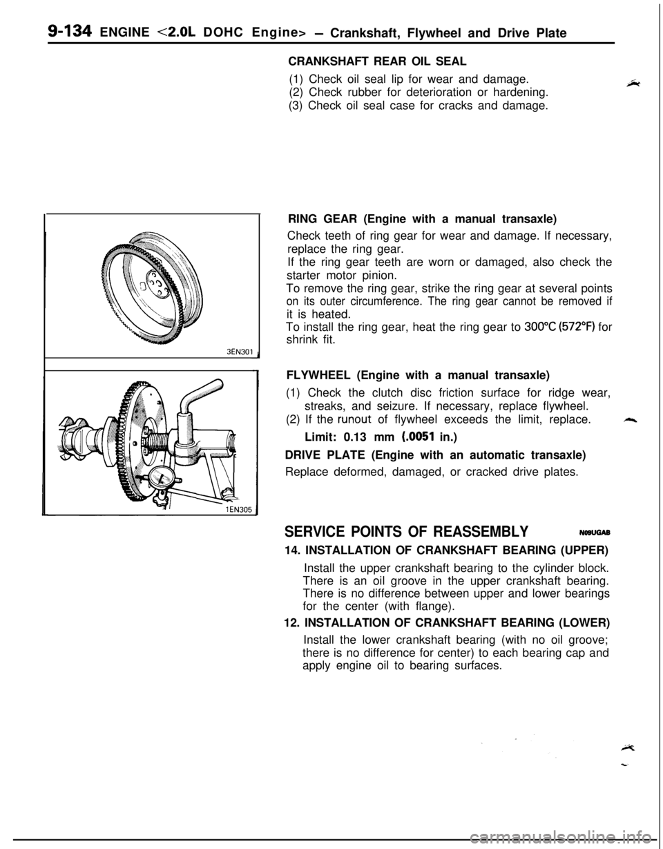
RING GEAR (Engine with a manual transaxle)
Check teeth of ring gear for wear and damage. If necessary,
replace the ring gear.
If the ring gear teeth are worn or damaged, also check the
starter motor pinion.
To remove the ring gear, strike the ring gear at several points
on its outer circumference. The ring gear cannot be removed ifit is heated.
To install the ring gear, heat the ring gear to
300°C (572°F) for
shrink fit.
FLYWHEEL (Engine with a manual transaxle)
(1) Check the clutch disc friction surface for ridge wear,
streaks, and seizure. If necessary, replace flywheel.
(2) If the
runout of flywheel exceeds the limit, replace.++.Limit: 0.13 mm
(.0051 in.)
DRIVE PLATE (Engine with an automatic transaxle)
Replace deformed, damaged, or cracked drive plates.
SERVICE POINTS OF REASSEMBLYNWUGAB
14. INSTALLATION OF CRANKSHAFT BEARING (UPPER)
Install the upper crankshaft bearing to the cylinder block.
There is an oil groove in the upper crankshaft bearing.
There is no difference between upper and lower bearings
for the center (with flange).
12. INSTALLATION OF CRANKSHAFT BEARING (LOWER)
Install the lower crankshaft bearing (with no oil groove;
there is no difference for center) to each bearing cap and
apply engine oil to bearing surfaces.
Page 419 of 1216

ENGINE <2.0L DOHC Engine> -Crankshaft, Flywheel and Drive Plate g-135
‘I. _
Front ofengine
(Timing
belt side)
BEN02
DEN063
6ENO48-
11. INSTALLATION OF BEARING CAP
(1) Verify the correct identification mark and the directionof the arrow for installation.
(2) After installing the bearing caps, make sure that the
crankshaft turns smoothly and the end play is correct. Ifthe end play exceeds the limit, replace crankshaft
bearings.Standard value:
0.05-0.18 mm (.0020-.0071 in.)
Limit: 0.25 mm
(.0098 in.)
10. INSTALLATION OF OIL SEALUsing the special tool, press-fit the oil seal into the
crankshaft rear oil case. Use a new oil seal.9. INSTALLATION OF OIL SEPARATOR
Force the oil separator into the oil seal case so that the oilhole in the separator is directed downward (arrow in
illustration).
Page 444 of 1216

INTeKE AND EXHAUST - Turbocharger
13. DISCONNECTION OF POWER STEERING OIL PUMP
Disconnect the oil pump with hoses from the bracket.
NOTE
The removed power steering oil pump should be fastened
(by using rope, etc.) in a position that will not interfere with
the removal/installation of the turbocharger assembly.
I05AOO26
29. REMOVAL OF TURBOCHARGER ASSEMBLY
Remove the turbocharger assembly with the exhaust fitting,water
pipe A, water pipe 6 and the oil pipe attached to it.3B.REMOVAL OF OIL PIPE
CautionAfter disconnecting the oil pipe, take care that foreign
material does not enter the oil passage hole of the
turbocharger assembly.
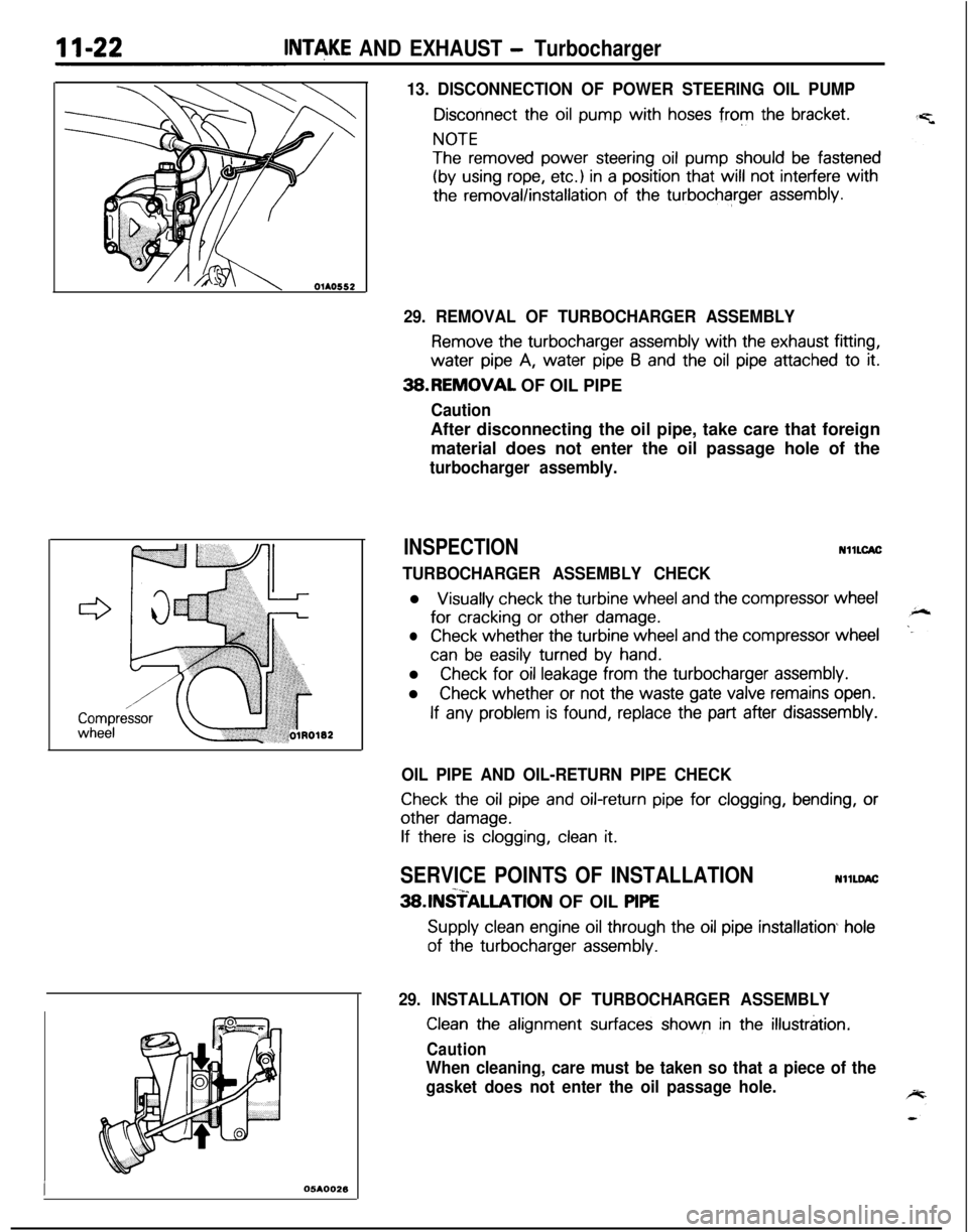
INSPECTIONNllLCAC
TURBOCHARGER ASSEMBLY CHECKl
Visually check the turbine wheel and the compressor wheelfor
cracking or other damage.
lCheck whether the turbine wheel and the compressor wheel
can be easily turned by hand.l
Check for oil leakage from the turbocharger assembly.l
Check whether or not the waste gate valve remains open.
If any problem is found, replace the part after disassembly.
OIL PIPE AND OIL-RETURN PIPE CHECK
Check the oil pipe and oil-return pipe for clogging, bending, or
other damage.
If there is clogging, clean it.
SERVICE POINTS OF INSTALLATIONNllLDAC-x_3SlNSTALLATlON OF OIL PlPE
Supply clean engine oil through the oil pipe installation hole
of the turbocharger assembly.
29. INSTALLATION OF TURBOCHARGER ASSEMBLY
Clean the alignment surfaces shown in the illustration.
Caution
When cleaning, care must be taken so that a piece of the
gasket does not enter the oil passage hole.
Page 446 of 1216

II-24INTAKE AND EXHAUST - TurbochargerSERVICE POINTS OF DISASSEMBLYNllLFAB
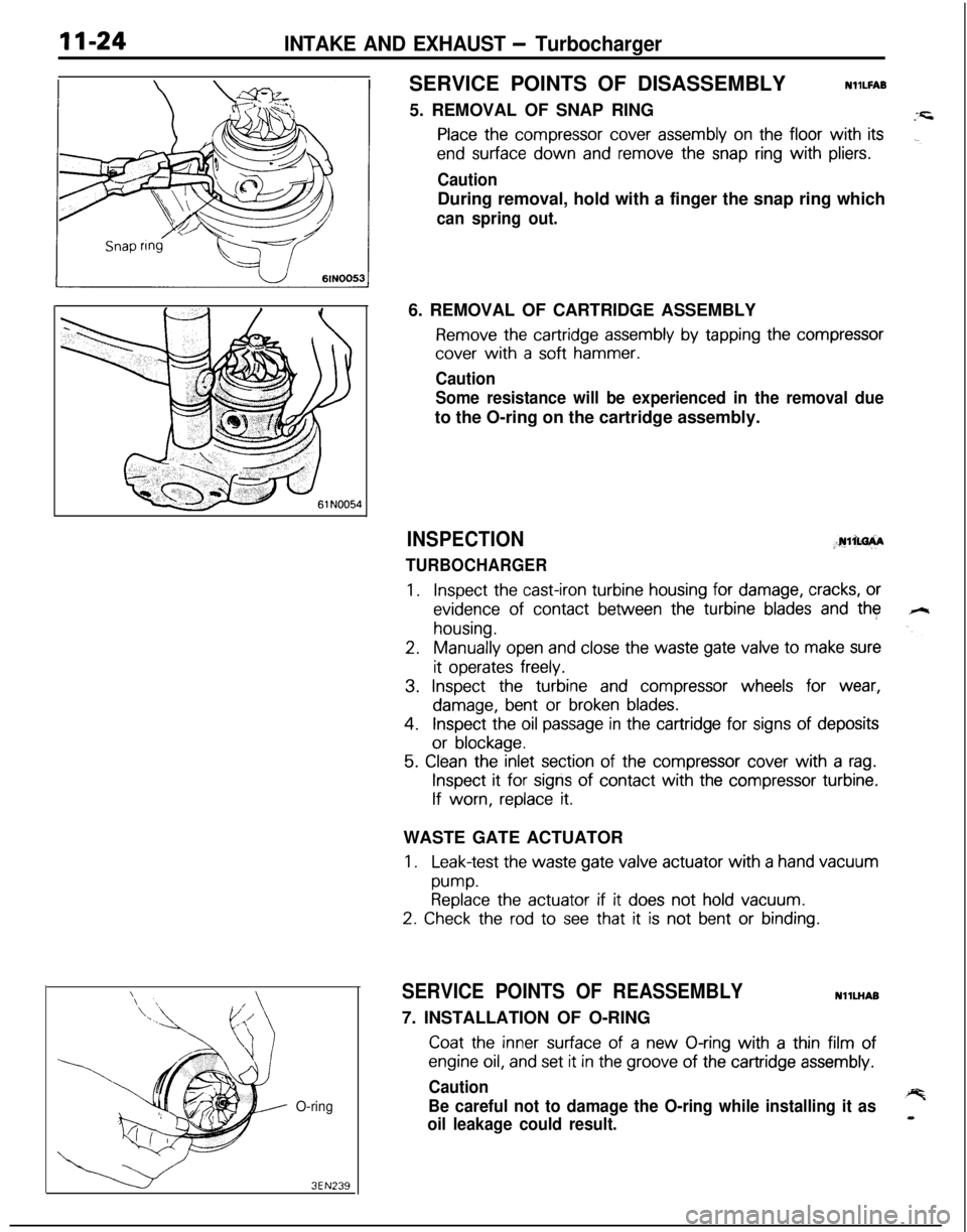
5. REMOVAL OF SNAP RING
Place the compressor cover assembly on the floor with its
end surface down and remove the snap ring with pliers.
CautionDuring removal, hold with a finger the snap ring which
can spring out.
O-ring
3EN2396. REMOVAL OF CARTRIDGE ASSEMBLY
Remove the cartridge assembly by tapping the compressor
cover with a soft hammer.
Caution
Some resistance will be experienced in the removal dueto the O-ring on the cartridge assembly.
INSPECTION;.rulim+A
TURBOCHARGER
1.Inspect the cast-iron turbine housing for damage, cracks, or
evidence of contact between the turbine blades and the
housing.
2.Manually open and close the waste gate valve to make sure
it operates freely.
3. Inspect the turbine and compressor wheels for wear,
damage, bent or broken blades.
4.Inspect the oil passage in the cartridge for signs of deposits
or blockage.
5. Clean the inlet section of the compressor cover with a rag.
Inspect it for signs of contact with the compressor turbine.
If worn, replace it.WASTE GATE ACTUATOR
1.Leak-test the waste gate valve actuator with a hand vacuum
pump.Replace the actuator if it does not hold vacuum.
2. Check the rod to see that it is not bent or binding.
SERVICE POINTS OF REASSEMBLYNllLHAB
7. INSTALLATION OF O-RING
Coat the inner surface of a new O-ring with a thin film of
engine oil, and set it in the groove of the cartridge assembly.
Caution
Be careful not to damage the O-ring while installing it as
oil leakage could result.
Page 447 of 1216

INTAKE AND EXHAUST - Turbocharger~1xz5
--=+I61 NO0706lN005E6.
INSTALLATIQN OF CARTRIDGE ASSEMBLY
(I1 Coat the outer circumference of the cartridge assembly
O-ring with a thin film of engine oil.
(29 Install the cartridge assembly on the compressor cover
by aligning the dowel pin.
CautionWhen installing the cartridge assembly on the
compressor cover, be careful not to damage the
compressor wheel blades.5. INSTALLATION OF SNAP RING
Place the cartridge assembly with the compressor cover
faced down and install the snap ring.
CautionInstall the snap ring with the tapered side of its outside
diameter up.4. INSTALLATION OF TURBINE HOUSING
Install the compressor cover and cartridge assembly on the
turbine housing with the dowel pin in alignment.
Caution
1. Be careful not to damage the blades of the turbine
wheel.
2. Be careful to install the turbine housing in the correct
direction.
TEST OF WASTE GATE ACTUATOR OPERATIONNllLlAA
Using a tester, apply a pressure to the actuator and make surethat the
rod moves.Standard value:
M/T76.7
kPa (11.1 psi)
A/T72.0
kPa (10.4 psi)
CautionDo not apply a pressure of more than 85.3
kPa (12.4 psi) to
the actuator. Otherwise, diaphragm may be damaged.
Never attempt to adjust the waste gate valve.
Page 495 of 1216

FUEL SYSTEM - Service Adjustment Procedures <1.8L Engine>l-4-41
SERVICE ADJUSTMENT PROCEDURES
CURB IDLE SPEED INSPECTION
CautionNlIFiiAE
The improper setting (throttle valve opening) will increase
exhaust gas temperature at deceleration, reducing catalystlife greatly and deteriorating exhaust gas cleaning per-
formance. It also has effect on fuel consumption and
engine braking.
ilter
Paper clip
16A0898
PI-e-conditions for inspection
0Engine coolant temperature: 85-95°C (185-205°F)
0Lights, electric cooling fan and accessories: OFF
l Transaxle: Neutral
(P for vehicles with an automatic
transaxle)l Steering wheel: Neutral position (vehicles with a power
steering)l Check ignition timing and adjust if necessary. Refer to
GROUP 8.
NOTEWith vehicles for Canada, the headlights and taillights, etc.
remain on even when the lighting switch is turned OFF, but thiscauses no problems during inspection.
(1) Insert the paper clip to the connector.
(2) Connect the tachometer to the inserted clip.
(3)Run the engine for more than 5 seconds at an engine speedof 2,000 to 3,000 rpm.
(4) Run the engine at idle for 2 minutes.
(5) Read the idling rpm. If it is not within the specified speed,
check the idle speed control system.
Curb idle speed: 700
f 100 rpm
NOTEAdjustment of the idling speed is usually unnecessary,
because this system controls the idling speed.
IDLE SPEED CONTROL AND
THROTlLE POSI-
TION SENSOR ADJUSTMENT
N14FIATAdjustment conditions
l Engine coolant temperature:
85-95X (185-205°F)
l Lights, electric cooling fan and accessories: Set to OFF
l Transaxle: Neutral (P for vehicles with an automatic
transaxle)l Steering wheel: Neutral position (vehicles with a power
steering)
(1) Slacken the accelerator cable enough.
(2) Connect a tachometer.
Page 502 of 1216

14-48FUEL SYSTEM - Service Adjustment Procedures <2.0L Engine>
SERVICE ADJUSTMENT PROCEDURES
<2.0L DOHC Engine>
CURB IDLE SPEED INSPECTION
Caution
N14FHADThe improper setting (throttle valve opening) will increase
exhaust gas temperature at deceleration, reducing
catalys-tic converter life greatly and deteriorating exhaust gas
cleaning performance. It also has effect on fuel ‘consump-
tion and engine braking.
Pre-conditions for inspection
l Engine coolant temperature:
85-95°C (185-205°F)
l Lights, electric cooling fan and accessories: OFF
lTransaxle: Neutral (P for vehicles with automatic transaxle)l Steering wheel: Neutral position (vehicles with a power-
steering)l Check ignition timing and adjust if necessary. Refer to
GROUP 8.
NOTEWith vehicles for Canada, the headlights and taillights, etc.
remain on even when the lighting switch is turned OFF, but thiscauses no problems during inspection.
(1) Connect the tachometer to the engine speed detection
terminal.
(2)Run the engine for more than 5 seconds at an engine speedof 2,000 to 3,000 rpm.
(3) Run the engine at idle for 2 minutes.
(4) Read the idling rpm. If it is not within the specified speed,
check the idle speed control system.
Curb idle speed:
750f 100 rpm
NOTE1. Adjustment of the idling speed is usually unnecessary,
because this system controls the idling speed.
2.For rpm, one-half of the actual engine rpm is indicated,so the actual engine rpm is two times the indicated
value shown by the tachometer.
BASIC IDLE SPEED ADJUSTMENT
N14FHBIPre-conditions for inspection
l Engine coolant temperature:
85-95°C (185-205°F)
l Lights, electric cooling fan, and accessories: OFF
lTransaxle: Neutral (P for vehicles with automatic transaxle)l Steerig wheel: Neutral position (vehicles with a
power-
steering)(1) Connect a tachometer.
Page 611 of 1216

1 pq
,s I’
:
REAR
SUSPENSION
LATERAL ROD.................................................11
REAR AXLE HUB............................................14
REARSUSPENSIONASSEMBLY..................5
SERVICE ADJUSTMENT PROCEDURES.......3Rear Hub Rotary-Sliding Resistance
(Torque)Adjustment.....................................4Rear Wheel Alignment Inspection
...............3Wheel Bearing End Play Adjustment
..........3
SHOCKABSORBERASSEMBLY...................8
SPECIAL TOOL................................................3
SPECIFICATIONS.............................................2
GeneralSpecifications..................................2
ServiceSpecifications...................................2Torque Specifications
...................................2
TORSION AXLE AND ARM ASSEMBLY......12
TROUBLESHOOTING......................................3
REARSUSPENSIONASSEMBLY . . . . . . . . . . . . . . . . . .21
SHOCK ABSORBER ASSEMBLY...................32
SERVICE ADJUSTMENT PROCEDURES.......20Rear WheelAlignment
Inspection................20
SPECIAL TOOLS.............................................18
SPECIFICATIONS.............................................16
GeneralSpecifications..................................16
ServiceSpecifications...................................16LTorqueSpecifications...................................17
Lubricant.......................................................17
STABILIZER BAR. . . . . . . . . . . . . . . . . . . . . . . . . . . . . . . . . . . . . . . . . . . . .35
TRAILING ARM. . . . . . . . . . . . . . . . . . . . . . . . . . . . . . . . . . . . . . . . . . . . . . .28
TROUBLESHOOTING......................................19
UPPER AND LOWER ARM............................25
CONTENTSN17AA-