Page 209 of 392

engagement while rotating adjusting screw to prevent burring screw slots. Ensure adjusting screw rotates
freely.
PARKING BRAKE
B2200 & B2600i
1. Depress brake pedal several times while vehicle is moving in Reverse. Ensure brakes are properly
adjusted. Pull parking brake lever with a force of 44 lbs. (20 kg). If stroke is 7-12 notches, parking brake
is properly adjusted.
2. If stroke is not 7-12 notches, raise and support rear of vehicle. Release parking brake lever. Loosen cable
lock nut at lever end of cable. Rotate adjusting nut until correct stroke is obtained. Operate parking brake
several times and ensure rear wheels rotate freely. Ensure parking brake warning light illuminates when
brake lever is pulled one notch.
Navajo
1. Adjust service brakes before adjusting parking brake cable. Ensure brake drums are cold. Apply parking
brake to fully depressed position. Grip threaded rod to prevent it from spinning.
2. Thread equalizer nut 6 full turns past its original position on threaded rod. See Fig. 4
. Check cable
tension at rear of equalizer assembly using Cable Tension Gauge (021-00018). If tension is not 400-600
lbs. (182-272 k
g), repeat step 2).
1991 Mazda MX-5 Miata
BRAKE SYSTEM 1991 BRAKES Mazda Brake System
Microsoft
Sunday, July 05, 2009 2:18:08 PMPage 6 © 2005 Mitchell Repair Information Company, LLC.
Page 210 of 392

Fig. 4: Adjusting Parking Brake (Navajo)
Courtesy of FORD MOTOR CO.
3. Release pedal, and check rear wheel drag. If drag is noted, remove drums, and check for clearance
between parking brake lever and cam plate. Cables should be tight enough to allow full application of rear
brakes and loose enough to allow full release of rear brakes.
929
1. Depress brake pedal several times. Pull parking brake lever with a force of 44 lbs. (20 kg). If stroke is 6-8
notches, parking brake is properly adjusted. If stroke is not 6-8 notches, adjust parking brake shoes. See
PARKING BRAKE SHOES under ADJUSTMENTS
.
NOTE: Tension limiter will reset parking brake tension any time system is
disconnected if distance between bracket and cinch strap hook is reduced
during adjustment. When adjustment has been performed so cinch strap
contacts bracket, system tension will increase greatly. This may cause an over-
tension condition. When available adjustment travel has been used, replace
tension limiter.
NOTE: If rear brake shoes are removed for any reason, parking brake cable
1991 Mazda MX-5 Miata
BRAKE SYSTEM 1991 BRAKES Mazda Brake System
Microsoft
Sunday, July 05, 2009 2:18:08 PMPage 7 © 2005 Mitchell Repair Information Company, LLC.
Page 211 of 392

2. Release parking brake lever. Using a screwdriver, reach through parking brake handle hole in console and
rotate adjusting screw until stroke is 6-8 notches. Ensure rear wheels rotate freely. Ensure parking brake
warning light illuminates when brake lever is pulled one notch.
Miata, MX-6, MPV, Protege, RX7, 323, 626
1. On models with rear disc brakes, depress brake pedal several times. On models with rear drum brakes,
start engine and depress brake pedal several times while vehicle is moving in Reverse. Stop engine.
2. On all models, pull parking brake lever with a force of 22 lbs. (10 kg). If stroke is 5-7 notches, parking
brake is properly adjusted. If stroke is not 5-7 notches, raise and support rear of vehicle. Release parking
brake lever.
3. Rotate cable adjusting nut at lever end of cable (under console cover) until stroke is within specification.
On models equipped with rear disc brakes, ensure clearance between stopper and lever (at each caliper) is
not less than .08" (2 mm) on RX7, or zero on all other models. On all models, ensure parking brake
warning light illuminates when brake lever is pulled one notch.
PARKING BRAKE SHOES
929
Raise and support vehicle. Remove rear wheels. Remove service plug from rotor. Using a screwdriver, rotate
star wheel adjuster toward axle until rotor locks. Rotate adjuster in opposite direction 3-5 notches. Ensure rotors
turn freely and parking brake functions properly. Install service plug and rear wheels.
PEDAL FREE PLAY
Depress pedal a few times to eliminate vacuum. Pedal free play should be .16-.28" (4-7 mm). Adjust play by
loosening push rod lock nut. Turn push rod until correct free play is obtained. Tighten push rod lock nut.
PEDAL HEIGHT & STOPLIGHT SWITCH
1. Released pedal height is measured from carpet surface on vertical portion of firewall to pedal pad center.
Disconnect stoplight switch electrical connector. Loosen lock nut on stoplight switch. Move switch away
from pedal. Loosen push rod lock nut. Turn rod until correct pedal height is obtained. See BRAKE
PEDAL HEIGHT SPECIFICATIONS .
2. Adjust pedal free play. See PEDAL FREE PLAY
under ADJUSTMENTS. Tighten push rod lock nut.
Rotate stoplight switch until it contacts pedal and then rotate an additional 1/2 turn. Tighten stoplight
switch lock nut. Reconnect stoplight switch electrical connector.
3. Applied pedal height is measured from angled portion of firewall (without carpet) to pedal pad center.
Start engine. On B2200, B2600i and MPV, depress brake pedal with 33 lbs. (15 kg) pressure. On all other
models, depress brake pedal with 132 lbs. (60 k
g) pressure. tension should be checked and adjusted.
NOTE: Pedal height and stoplight switch information is not available for Navajo.
1991 Mazda MX-5 Miata
BRAKE SYSTEM 1991 BRAKES Mazda Brake System
Microsoft
Sunday, July 05, 2009 2:18:08 PMPage 8 © 2005 Mitchell Repair Information Company, LLC.
Page 212 of 392

4. On all models, measure applied pedal height. If distance is not as specified, check brake adjustment or
system for air. See BRAKE PEDAL HEIGHT SPECIFICATIONS TABLE.
BRAKE PEDAL HEIGHT SPECIFICATIONS
TESTING
POWER BRAKE UNIT
1. With engine off, depress brake pedal several times. Press and hold brake pedal and start engine. If brake
pedal moves down slightly immediately after engine starts, power brake unit is operating. If brake pedal
does not move as specified, go to next step.
2. Run engine for 1-2 minutes. Stop engine. Press brake pedal several times and note if first pedal stroke is
longer than subsequent strokes. If first pedal stroke is longer than subsequent strokes, power brake unit is
operating. If length of strokes is equal, test check valve and vacuum hose between vacuum source and
power brake unit. Repair as necessary, and go to next step.
3. Start engine. Press and hold brake pedal. Stop engine. Hold pedal down for about 30 seconds. If pedal
height remains at same height, power brake unit is operating. If pedal height recedes, test check valve and
vacuum hose between vacuum source and power brake unit. Repair as necessary.
REMOVAL & INSTALLATION
FRONT DISC BRAKE PADS
Removal & Installation (Protege & 323)
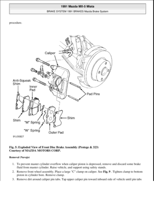
Raise and support front of vehicle. Remove wheels. Remove spring "A". See Fig. 5 . Remove spring "B".
Remove pad pins. Remove pads, shims and anti-squeak shim. Replace pad if lining thickness is less than
specified. See MINIMUM PAD LINING SPECIFICATIONS (FRONT) TABLE. To install, reverse removal
ApplicationIn. (mm)
Pedal Released
B2200 & B2600i7.1-7.3 (180-185)
Miata, MX-6, 626 & 9296.7-7.1 (171-181)
MPV7.5-7.9 (191-201)
Protege & 3237.6-7.7 (193-196)
RX77.2-7.4 (184-189)
Pedal Applied (1)
B2200 & B2600i4.1 (105)
Miata, MX-6, 626 & 9293.7 (95)
MPV5.2 (133)
Protege & 3232.8 (70)
RX73.9 (100)
(1)Minimum height.
1991 Mazda MX-5 Miata
BRAKE SYSTEM 1991 BRAKES Mazda Brake System
Microsoft
Sunday, July 05, 2009 2:18:08 PMPage 9 © 2005 Mitchell Repair Information Company, LLC.
Page 213 of 392
procedure.
Fig. 5: Exploded View of Front Disc Brake Assembly (Protege & 323)
Courtesy of MAZDA MOTORS CORP.
Removal (Navajo)
1. To prevent master cylinder overflow when caliper piston is depressed, remove and discard some brake
fluid from master cylinder. Raise vehicle, and support using safety stands.
2. Remove front wheel assembly. Place a large "C" clamp on caliper. See Fig. 9
. Tighten clamp to bottom
piston in cylinder bore. Remove clamp.
3. Remove dirt around caliper pin tabs. Tap upper caliper pin toward inboard side of vehicle until pin tabs
1991 Mazda MX-5 Miata
BRAKE SYSTEM 1991 BRAKES Mazda Brake System
Microsoft
Sunday, July 05, 2009 2:18:08 PMPage 10 © 2005 Mitchell Repair Information Company, LLC.
Page 214 of 392

touch spindle face.
4. Insert screwdriver into slot provided behind pin tabs on inboard side of pin. Using pliers, compress end of
pin while using screwdriver to pry until tabs slip into spindle groove.
5. Place a 7/16" diameter punch on end of pin, and drive caliper pin out of caliper slide groove. Repeat
procedure for lower pin. Remove caliper from rotor. Remove outer brake pad. Compress anti-rattle spring
clip, and remove inner brake pad. Support caliper aside. Replace pad if lining thickness is less than
specified. See MINIMUM PAD LINING SPECIFICATIONS (FRONT) TABLE.
Installation
Use "C" clamp to push caliper piston into piston bore until it bottoms out. To install, reverse removal procedure.
Bleed air from brake system.
Removal & Installation (RX7 With 4-Piston Caliper)
Raise and support front of vehicle. Remove wheels. Remove pad pins and pad springs. See Fig. 6 . Remove
brake pads and shims. Replace pad if lining thickness is less than specified. See MINIMUM PAD LINING
SPECIFICATIONS (FRONT) . To install, reverse removal procedure. CAUTION: During installation, DO NOT tap caliper pin too far into spindle groove. If
this happens, tap pin in other direction until tabs snap back into place.
Tabs on each end of caliper pin must be free to catch on spindle flanks.
1991 Mazda MX-5 Miata
BRAKE SYSTEM 1991 BRAKES Mazda Brake System
Microsoft
Sunday, July 05, 2009 2:18:08 PMPage 11 © 2005 Mitchell Repair Information Company, LLC.
Page 215 of 392
Fig. 6: Front Disc Brake Assembly (RX7 with 4-Piston Caliper)
Removal & Installation (All With Single-Piston Caliper)
Raise and support front of vehicle. Remove wheels. Remove lower lock pin/guide bolt. See Fig. 7 , Fig. 8 , Fig.
10 , Fig. 11 , or Fig. 12 . Pivot caliper upward, and support using rope. Remove brake pads. Replace pad if
lining thickness is less than specified. See MINIMUM PAD LINING SPECIFICATIONS (FRONT) TABLE.
To install, reverse removal procedure.
MINIMUM PAD LINING SPECIFICATIONS (FRONT)
ApplicationThickness In. (mm)
B2200, B2600i & Navajo.12 (3.0)
1991 Mazda MX-5 Miata
BRAKE SYSTEM 1991 BRAKES Mazda Brake System
Microsoft
Sunday, July 05, 2009 2:18:08 PMPage 12 © 2005 Mitchell Repair Information Company, LLC.
Page 216 of 392
Fig. 7: View of Front Disc Brake Assembly B2200 & B2600I
Miata.04 (1.0)
MPV, MX-6, Protege, RX7, 323, 626 & 929.08 (2.0)
NOTE: The following figures are Courtesy Mazda Motors Corp.
1991 Mazda MX-5 Miata
BRAKE SYSTEM 1991 BRAKES Mazda Brake System
Microsoft
Sunday, July 05, 2009 2:18:08 PMPage 13 © 2005 Mitchell Repair Information Company, LLC.