Page 305 of 392

1. Raise and support vehicle. Remove wheel assembly. Remove axle lock nut. Remove cotter pin, and
disconnect tie rod from steering knuckle. Remove and wire aside brake caliper.
2. Separate lower control arm from ball joint. Remove bolt attaching ball joint to steering knuckle. Remove
bolts retaining steering knuckle to strut assembly. Separate hub and knuckle from drive shaft. Remove
wheel hub and rotor from knuckle. Remove bearings and oil seals.
Removal (MX-6 & 626)
1. Raise and support vehicle. Remove wheel assembly. Disconnect tie rod end from steering knuckle.
Disconnect stabilizer bar from lower control arm. Remove axle lock nut.
2. Disconnect brake line from strut assembly. Remove and wire aside brake caliper. Remove wheel speed
sensor. Remove bolt attaching ball joint to steering knuckle. Remove bolts attaching steering knuckle to
strut assembly. Remove steering knuckle.
3. Remove wheel hub from knuckle using Puller Set (49-G033-1A1). Remove snap ring. Remove wheel
bearing from steering knuckle using Remover (49-G033-106).
Removal (Protege, 323 & 929)
1. Raise and support vehicle. Remove wheel assembly. Remove axle lock nut. Remove cotter pin, and
disconnect tie rod from steering knuckle. Remove and wire aside brake caliper. Separate lower control
arm from ball joint. Remove bolts retaining steering knuckle to strut assembly.
2. On Protege and 323, separate hub and knuckle from drive shaft. Remove wheel hub and rotor from
knuckle. Place alignment marks on rotor and wheel hub. Separate and remove dust cover. Remove
bearings, oil seals, bearing outer races and spacer.
3. On 929, remove hub and rotor. Remove grease seal, sensor ring and circlip. Press bearing from hub
assembly. DO NOT reuse old bearing once pressed from hub.
Removal (RX7)
Raise and support vehicle. Remove wheel assembly. Remove and wire aside brake caliper. Remove grease cap,
cotter pin, nut lock and spindle nut. Remove washer and outer wheel bearing. Remove hub and rotor assembly.
Remove wheel speed sensor ring. Remove inner oil seal and wheel bearing.
Inspection (All Models)
Wash all disassembled parts before inspection. Check for damage, excessive wear and signs of bearing seizure.
Inspect steering knuckle and hub for cracks, scoring and rust. Check for damaged dust cover and poor fit with
steering knuckle.
Installation (All Models)
To install, reverse removal procedure. Adjust wheel bearing preload. See WHEEL BEARING under
ADJUSTMENTS & INSPECTION
. NOTE: If bearings need to be replaced on RX7, also replace hub.
1991 Mazda MX-5 Miata
SUSPENSION - FRONT 1990-91 SUSPENSION Front
Microsoft
Sunday, July 05, 2009 2:08:54 PMPage 7 © 2005 Mitchell Repair Information Company, LLC.
Page 306 of 392

LOWER CONTROL ARM
Removal
Raise and support vehicle. Remove wheel assembly. Remove engine splash shield (if equipped). Remove
stabilizer bar from lower control arm. Remove strut rod (if equipped). Remove ball joint clamp bolt or pivot
nut, and separate ball joint from steering knuckle. Remove lower control arm pivot bolts. Remove lower control
arm.
Inspection
Check lower control arm for damage or cracks. Check bushings for deterioration and excessive wear. Check
ball joint for excessive wear. Examine dust boot for damage. Replace parts as necessary.
Bushing Replacement (Miata)
Cut or press old bushing from control arm. Coat new bushing with paraffin-based oil. Press new bushing into
control arm. To install, reverse removal procedure.
Bushing Replacement (MPV 4WD)
Cut away bushing inner collar. Using a vise and Remover/Installer (49-G033-102 and 49-FO27-009), push out
front bushing. Press out rear bushing using a press and Remover/Installer (49-U034-202 and 49-GO26-103). To
install front bushing, apply soapy water to bushing and use remover/installer to press in. To install rear bushing,
align arrows on bushing with marks on lower arm and use remover/installer to press in.
Bushing Replacement (MX-6 & 626)
Cut away bushing inner collar. Using a vise and Remover/Installer (49-GO34-2A0), push out bushing. To
install, apply soapy water to bushing and use remover/installer to press in. Always install bushing from outer
side of arm. Press in bushing until collar contacts arm.
Bushing Replacement (Protege & 323)
Using a vise and Remover/Installer Set (49-BO34-2A0), push out bushing. To install, apply soapy water to
bushing and use remover/installer to press in. Always install bushing from outer side of arm. Press in bushing
until collar contacts arm.
Bushing Replacement (929)
Cut away bushing outer collar. Using a vise and Remover/Installer (49-HO34-202 and 49-HO34-201), remove
bushing from control arm. To install, reverse removal procedure.
Bushing Replacement (RX7)
NOTE: Lower control arm bushings are not replaceable on MPV 2WD models. Replace
control arm assembly if bushings are worn or damaged.
1991 Mazda MX-5 Miata
SUSPENSION - FRONT 1990-91 SUSPENSION Front
Microsoft
Sunday, July 05, 2009 2:08:54 PMPage 8 © 2005 Mitchell Repair Information Company, LLC.
Page 307 of 392

Push out front bushing using a press and Remover (49-G030-627A). To remove rear bushing, install Bearing
Puller (49-0710-520) on bushing. DO NOT overtighten bearing puller nuts or lower arm will be distorted and
damaged. Press to push out rear bushing using Remover (49-G030-627A). To install both bushings, use
remover and Support Block (49-0823-146).
Installation (All Models)
To install, reverse removal procedure. Tighten lower control arm pivot bolts to specification with vehicle
resting on ground and suspension unloaded. See TORQUE SPECIFICATIONS
.
UPPER CONTROL ARM
Removal (Miata)
Raise and support vehicle. Remove wheel assembly. Remove engine splash shield. Remove ball joint pivot nut.
Use Puller (49-0118-850C) to separate ball joint from steering knuckle. Remove upper control arm pivot bolts.
Remove upper control arm.
Inspection
Check upper control arm for damage or cracks. Check bushings for deterioration and excessive wear. Check
ball joint for excessive wear. Examine dust boot for damage. Replace parts as necessary.
Bushing Replacement
Using a chisel, remove old bushing from control arm. Coat new bushing with grease. Press new bushing into
control arm.
Installation
To install, reverse removal procedure. Tighten upper control arm pivot bolts to specification with vehicle
resting on ground and suspension unloaded.
SHOCK ABSORBER
Removal (Miata)
Raise and support vehicle. Remove wheel assembly. Remove engine splash shield. Remove stabilizer link bolt.
Separate upper ball joint from steering knuckle. Loosen lower control arm pivot bolts. Remove shock absorber
upper mount nuts and lower bolt. Move lower control arm just enough to remove shock absorber. Be careful not
to damage brake line.
Disassembly
Clamp upper mount in vise. Loosen lock nut 2 turns only. Compress coil spring using coil spring compressor.
Remove lock nut and remainin
g components. Slowly release compressor tension.
1991 Mazda MX-5 Miata
SUSPENSION - FRONT 1990-91 SUSPENSION Front
Microsoft
Sunday, July 05, 2009 2:08:54 PMPage 9 © 2005 Mitchell Repair Information Company, LLC.
Page 308 of 392

Inspection
Check for damage, oil leakage and abnormal noise. Check rubber parts for deterioration or damage. Inspect coil
spring for signs of fatigue or damage. Replace parts as needed.
Reassembly
Clamp shock absorber in vise. Install coil spring and components in reverse order of disassembly. Ensure coil
spring is well seated in upper and lower spring seats.
Installation
To install, reverse removal procedure. Final tighten all bolts with vehicle resting on ground and suspension
unloaded. See appropriate See SPECIFICATIONS & PROCEDURES article in the WHEEL ALIGNMENT
section for checks and adjustments.
STRUT ASSEMBLY
Removal
1. Raise and support vehicle. Remove wheel assembly. Disconnect brake line from strut assembly. Remove
bolts attaching steering knuckle arm to strut assembly.
2. Disconnect harness connector from actuator (if equipped). Remove bolts, actuator and actuator mounting
bracket from upper mounting block. Remove nuts attaching upper strut assembly to body panel. Remove
strut assembly.
Disassembly
Clamp strut in vise. Compress coil spring using coil spring compressor. Remove piston lock nut. Slowly release
compressor tension. Remove components. Remove coil spring. Remove strut from vise.
Inspection
Check strut tube for cracks, damage, oil leakage and abnormal noise. Check rubber parts for deterioration or
damage. Inspect coil spring for signs of fatigue or damage. Check actuator control rod of strut assembly for
smooth rotation (if equipped). Replace parts as needed.
Reassembly
Clamp strut in vise. Install coil spring and components in reverse order of disassembly. Ensure that coil spring
is well seated in upper and lower spring seats. On MX-6 and 626, ensure upper spring seat positioning hole
faces inside of vehicle. NOTE: Prior to removing strut-to-steering knuckle bolts, make an alignment mark for
reassembly reference. Note position of mounting mark on top of strut assembly
before removing strut.
1991 Mazda MX-5 Miata
SUSPENSION - FRONT 1990-91 SUSPENSION Front
Microsoft
Sunday, July 05, 2009 2:08:54 PMPage 10 © 2005 Mitchell Repair Information Company, LLC.
Page 309 of 392
Installation
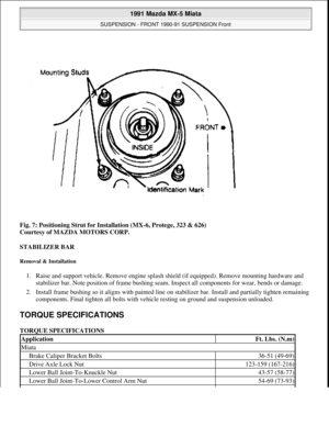
To install, reverse removal procedure. Place identification mark of mounting block in its original position. See
Fig. 6
or Fig. 7 . See appropriate See SPECIFICATIONS & PROCEDURES article in the WHEEL
ALIGNMENT section for checks and adjustments.
Fig. 6: Positioning Strut for Installation (MPV, RX7 & 929)
Courtesy of MAZDA MOTORS CORP.
1991 Mazda MX-5 Miata
SUSPENSION - FRONT 1990-91 SUSPENSION Front
Microsoft
Sunday, July 05, 2009 2:08:54 PMPage 11 © 2005 Mitchell Repair Information Company, LLC.
Page 310 of 392
Fig. 7: Positioning Strut for Installation (MX-6, Protege, 323 & 626)
Courtesy of MAZDA MOTORS CORP.
STABILIZER BAR
Removal & Installation
1. Raise and support vehicle. Remove engine splash shield (if equipped). Remove mounting hardware and
stabilizer bar. Note position of frame bushing seam. Inspect all components for wear, bends or damage.
2. Install frame bushing so it aligns with painted line on stabilizer bar. Install and partially tighten remaining
components. Final tighten all bolts with vehicle resting on ground and suspension unloaded.
TORQUE SPECIFICATIONS
ApplicationFt. Lbs. (N.m)
Miata
Brake Caliper Bracket Bolts36-51 (49-69)
Drive Axle Lock Nut123-159 (167-216)
Lower Ball Joint-To-Knuckle Nut43-57 (58-77)
Lower Ball Joint-To-Lower Control Arm Nut54-69 (73-93)
1991 Mazda MX-5 Miata
SUSPENSION - FRONT 1990-91 SUSPENSION Front
Microsoft
Sunday, July 05, 2009 2:08:54 PMPage 12 © 2005 Mitchell Repair Information Company, LLC.
Page 311 of 392

Lower Control Arm-To-Frame54-69 (73-93)
Lug Nuts65-87 (88-118)
Stabilizer Bar Bolts (Frame)13-19 (18-26)
Stabilizer Bar Link Bolts27-40 (36-54)
Shock Absorber Assembly-To-Body Nuts21-27 (29-36)
Shock Absorber Lower Bolt54-69 (73-93)
Shock Absorber Lock Nut23-34 (31-46)
Tie Rod-To-Knuckle Nut21-32 (29-44)
Upper Ball Joint-To-Knuckle Nut30-46 (41-62)
Upper Control Arm-To-Frame87-102 (118-138)
MPV
Ball Joint-To-Lower Control Arm Bolt (4WD)75-101 (102-137)
Ball Joint-To-Lower Control Arm Nut (4WD)94-127 (128-172)
Brake Caliper Bracket Bolts65-80 (88-108)
Drive Axle Lock Nut131-173 (177-235)
Lower Control Arm-To-Frame (2WD)94-108 (127-146)
Lower Control Arm-To-Frame (4WD)101-127 (137-172)
Lug Nuts65-87 (88-118)
Stabilizer Bar Bolts (Frame) (2WD)37-45 (50-61)
Stabilizer Bar Bolts (Frame) (4WD)14-19 (19-26)
Strut Assembly Lock Nut47-59 (64-80)
Strut Assembly-To-Body Nuts21-27 (29-36)
Strut Assembly-To-Knuckle Bolt69-86 (93-117)
Strut Rod Body Bushing Bolt61-76 (83-103)
Strut Rod-To-Body Nut108-127 (146-172)
Strut Rod-To-Lower Control Arm76-92 (103-125)
Tie Rod-To-Knuckle Nut44-58 (59-78)
MX-6 & 626
Ball Joint-To-Steering Knuckle Nut27-40 (36-54)
Brake Caliper Bracket Bolts58-72 (78-98)
Drive Axle Lock Nut173-235 (235-319)
Lower Control Arm-To-Frame58-78 (78-106)
Lug Nuts65-87 (88-118)
Stabilizer Bar Bolts (Frame)27-40 (36-54)
Strut Assembly Lock Nut47-59 (64-80)
Strut Assembly-To-Body Nuts34-46 (46-63)
Strut Assembly-To-Knuckle Bolt69-86 (93-117)
Tie Rod-To-Knuckle Nut31-42 (42-57)
Wheel Speed Sensor Bolt12-17 (16-23)
Protege & 323
Ball Joint-To-Lower Control Arm Nut69-86 (93-117)
1991 Mazda MX-5 Miata
SUSPENSION - FRONT 1990-91 SUSPENSION Front
Microsoft
Sunday, July 05, 2009 2:08:54 PMPage 13 © 2005 Mitchell Repair Information Company, LLC.
Page 312 of 392

32-44 (43-59)
Brake Caliper Bracket Bolts29-36 (39-49)
Drive Axle Lock Nut173-235 (235-319)
Lower Control Arm-To-Frame
Front69-86 (93-117)
Rear69-94 (93-127)
"U" Bracket Bolts69-86 (93-117)
Lug Nuts65-87 (88-118)
Stabilizer Bar Bolts (Frame)32-44 (43-59)
Strut Assembly Lock Nut58-81 (79-110)
Strut Assembly-To-Body Nuts21-30 (29-40)
Strut Assembly-To-Knuckle Bolt69-93 (93-127)
Tie Rod-To-Knuckle Nut31-42 (42-57)
RX7
Ball Joint-To-Steering Knuckle Nut27-40 (36-54)
Brake Caliper Bracket Bolts58-72 (78-98)
Lower Control Arm-To-Frame
Front46-69 (63-93)
Rear51-61 (69-83)
Lug Nuts65-87 (88-118)
Stabilizer Bar Bolts (Frame)13-19 (18-26)
Stabilizer Bar Link Bolts27-40 (36-54)
Strut Assembly Lock Nut47-59 (64-80)
Strut Assembly-To-Body Nuts21-27 (29-36)
Strut Assembly-To-Knuckle Bolt69-86 (93-117)
Tie Rod-To-Knuckle Nut21-32 (29-44)
929
Ball Joint-To-Steering Knuckle Nut69-91 (94-123)
Brake Caliper Bracket Bolts58-86 (78-117)
Drive Axle Lock Nut72-130 (98-177)
Front Wheel Bearing Nut72-130 (98-177)
Knuckle Arm-To-Knuckle75-101 (102-137)
Lower Control Arm-To-Frame55-69 (74-93)
Lug Nuts65-87 (88-118)
Stabilizer Bar Bolts (Frame)37-45 (50-61)
Strut Assembly Lock Nut47-59 (64-80)
Strut Assembly-To-Body Nuts25-32 (34-44)
Strut Assembly-To-Knuckle Bolt69-86 (93-117)
Strut Rod Body Bushing Bolt69-86 (93-117)
Strut Rod-To-Body Nut64-86 (93-117)
Strut Rod-To-Lower Control Arm76-92 (103-125)
1991 Mazda MX-5 Miata
SUSPENSION - FRONT 1990-91 SUSPENSION Front
Microsoft
Sunday, July 05, 2009 2:08:54 PMPage 14 © 2005 Mitchell Repair Information Company, LLC.