Page 3989 of 4087

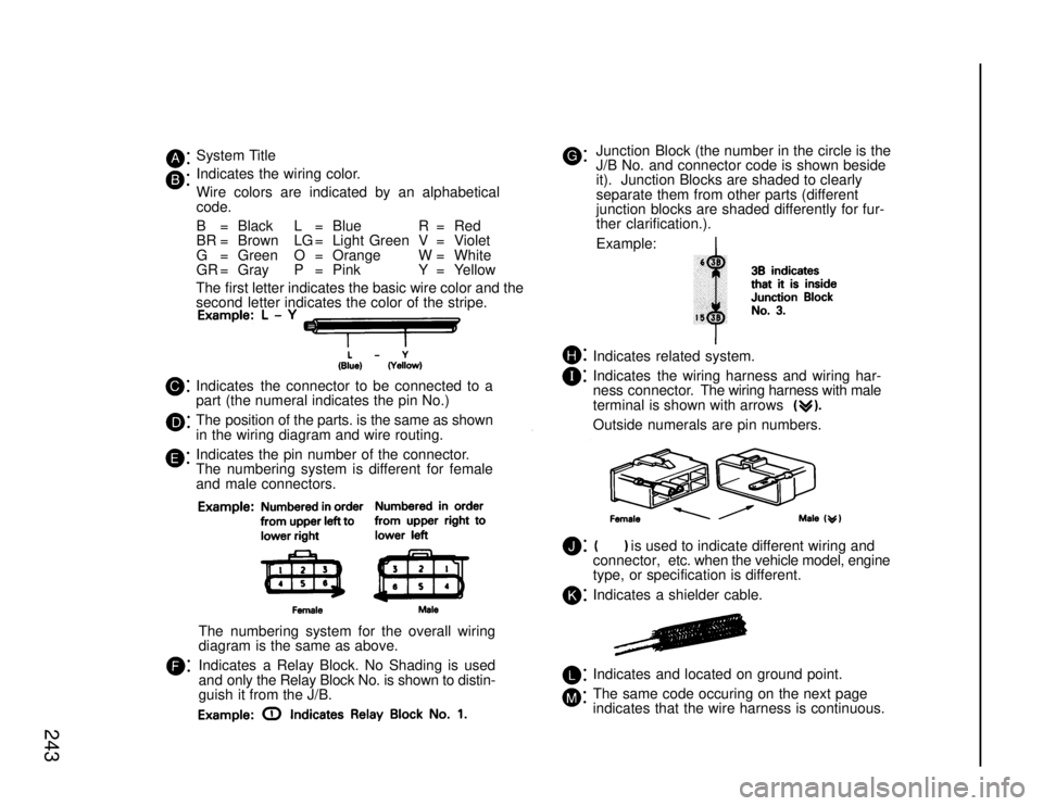
Junction Block (the number in the circle is the
J/B No. and connector code is shown beside
it). Junction Blocks are shaded to clearly
separate them from other parts (different
junction blocks are shaded differently for fur-
ther clarification.).
Example:
Indicates related system.
Indicates the wiring harness and wiring har-
ness connector. The wiring harness with male
terminal is shown with arrows
Outside numerals are pin numbers.
is used to indicate different wiring and
connector, etc. when the vehicle model, engine
type, or specification is different.
Indicates a shielder cable.
Indicates and located on ground point.
The same code occuring on the next page
indicates that the wire harness is continuous.
System Title
Indicates the wiring color.
Wire colors are indicated by an alphabetical
code.
B = Black L = Blue R = Red
BR = Brown LG = Light Green V = Violet
G = Green O = Orange W = White
GR = Gray P = Pink Y = Yellow
The first letter indicates the basic wire color and the
second letter indicates the color of the stripe.
Indicates the connector to be connected to a
part (the numeral indicates the pin No.)
The position of the parts. is the same as shown
in the wiring diagram and wire routing.
Indicates the pin number of the connector.
The numbering system is different for female
and male connectors.
The numbering system for the overall wiring
diagram is the same as above.
Indicates a Relay Block. No Shading is used
and only the Relay Block No. is shown to distin-
guish it from the J/B.
243
WhereEverybodyKnowsYourName
Page 3990 of 4087

244
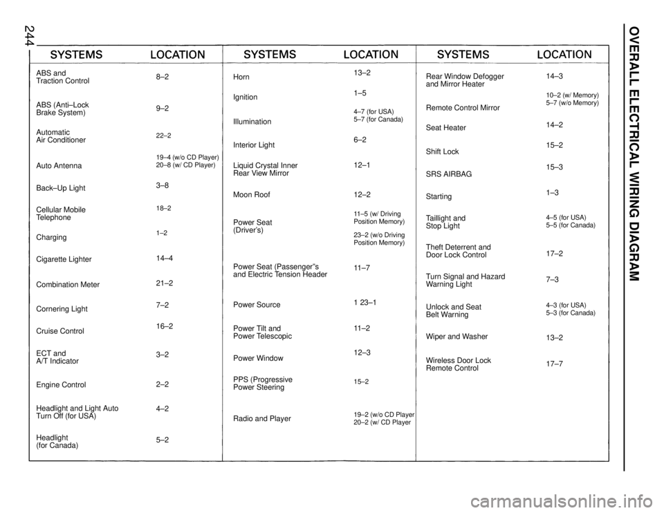
Rear Window Defogger
and Mirror Heater
Remote Control Mirror
Seat Heater
Shift Lock
SRS AIRBAG
Starting
Taillight and
Stop Light
Theft Deterrent and
Door Lock Control
Turn Signal and Hazard
Warning Light
Wiper and Washer
Wireless Door Lock
Remote Control
Horn
Ignition
Illumination
Interior Light
Liquid Crystal Inner
Rear View Mirror
Moon Roof
Power Seat
(Driver's)
Power Source
Power Window
PPS (Progressive
Power Steering
Radio and Player
ABS and
Traction Control
Automatic
Air Conditioner
Auto Antenna
Back±Up Light
Cellular Mobile
Telephone
Charging
Cigarette Lighter
Combination Meter
Cruise Control
Headlight and Light Auto
Turn Off (for USA)
Headlight
(for Canada) ECT and
A/T Indicator
4±2 16±2 7±2
3±2 21±2 3±8
14±4
18±2 19±4 (w/o CD Player)
20±8 (w/ CD Player)9±2 8±2
4±7 (for USA)
5±7 (for Canada)11±2
12±311±5 (w/ Driving
Position Memory)11±7 12±1 1±5 13±2
6±2 15±2 14±2
13±2
17±7 7±3 17±2 15±3
1±315±2
Power Tilt and
Power Telescopic12±2
Power Seat (Passengerºs
and Electric Tension Header
5±2 2±2
Cornering Light ABS (Anti±Lock
Brake System)
22±2
Engine Control Unlock and Seat
Belt Warning
1±2
23±2 (w/o Driving
Position Memory)
1 23±119±2 (w/o CD Player
20±2 (w/ CD Player
14±310±2 (w/ Memory)
5±7 (w/o Memory)
4±3 (for USA)
5±3 (for Canada) 4±5 (for USA)
5±5 (for Canada)
OVERALL ELECTRICAL WIRING DIAGRAM
WhereEverybodyKnowsYourName
Page 3991 of 4087

44
POWER SOURCE (Current Flow Chart)
The chart below shows the route by which current flows from the battery to \
each electrical source
(Fusible Link, Circuit Breaker, Fuse, etc.) and other parts.
The next page and following pages show the parts to which each electrica\
l source outputs current.
Taillight
Relay (Point Side)
30A AM260A MAIN 50A DEFOG
60A HEATER
7.5 TRAC
40A IG SW
120A ALT
Starter Relay
(Point Side)
Headlight Relay
(Point Side)
30A EFI
15A TEL
10A DOME
20A RADIO No. 1
25A HAZ±HORN
Theft Deterrent and
Door Lock ECU
15A HEAD RH
(USA) 15A HEAD LH
(USA)
Dimmer Relay
(Coil Side)
Starter
15A STOPIgnition SW
(AM1)
30A DOOR
15A TAIL
Alternator
ABS Motor Relay
(Point Side)
Defogger
Relay
Starter ABS
Actuator
10A MIR±HTR
15A ECU±B 7.5A PANEL
7.5 IGN
Engine ECU Traction Brake
Actuator
30A INJ
60A ABS No.1
Traction Brake
Main Relay
(Point Side)
ABS
Actuator Relay
30A POWER
Integration
Relay
100A AM1
Seat Heater
Relay (Point Side)
7.5 ALT SENCING
30A ABS No.2 Headlight
Relay
(Coil Side)
Traction Motor
Relay (Point Side)Traction Pump
and Motor Dimmer Relay
(Point Side) Ignition SW
(AM2)
Taillight
Relay (Coil Side)
15A HEAD (LH±LWR)
(CANADA)
15A HEAD (RH±LWR)
(CANADA)
Engine and
ECT ECU
15A HEAD (LH±UPR)
(CANADA)
15A HEAD (RH±UPR)
(CANADA) ABS and
Traction ECU
Battery
[LOCATION](1): J/B No. 1 (See page
20)(2): R/B No. 2 (See page 19)(3): R/B No. 4 (See page 23)
20
19 22
WhereEverybodyKnowsYourName
Page 3992 of 4087
45
Light Control
SW
ABS and
Traction ECU
Diode
Theft Deterrent
and Door Lock ECU
Integration
Relay Noise Filter
(for Ignition
System
Injector No. 3
Injector No. 4 Igniter
7.5 ST 15A SEAT±HTR Ignition Coil
Injector No. 1
Injector No. 2
Injector No. 5
Injector No. 6
ABS
Actuator
7.5A ENGINE
15A ECU±IG
10A GAUGE 20A WIPER 20A TURN 10A HEATER 7.5A RADIO No.2
15A CIG
(4): R/B No. 6 (See page )(5): Fuse Block (F9 See page 19 )
24 19
WhereEverybodyKnowsYourName
Page 3993 of 4087

46
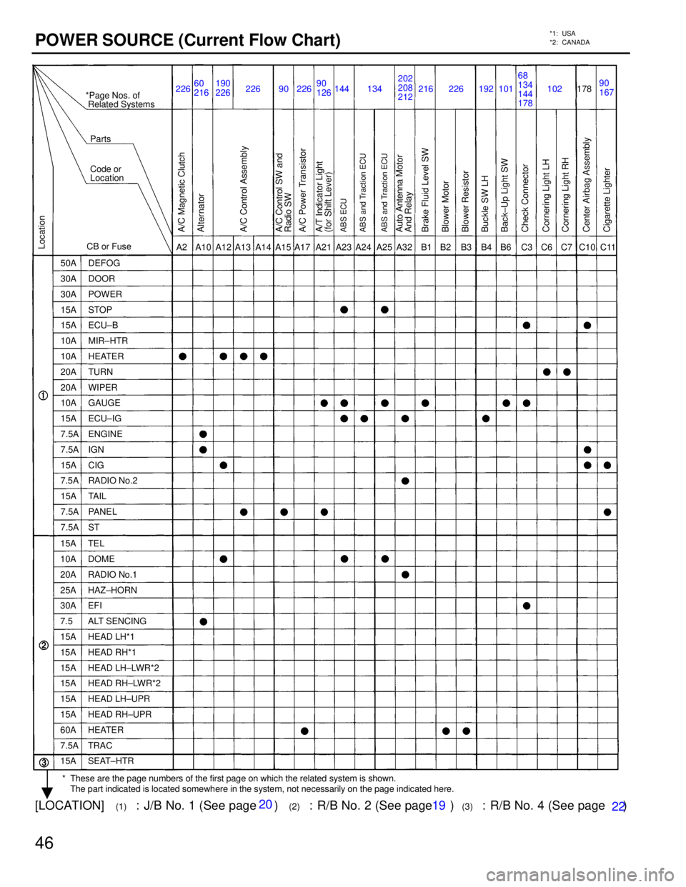
POWER SOURCE (Current Flow Chart)*1: USA
*2: CANADA
60
216
226
192178
226 90 144 134 216 102 202
208
212 90
167
A2 A15 C6 B2
B1
A10 A14 A12 A17A13 A23 A24 A25 A32 C11 B3 B4 B6 C3 C10C7
A21
Blower Resistor Auto Antenna Motor
And Relay A/C Magnetic Clutch
Alternator
A/C Control Assembly
A/C Power Transistor
A/T Indicator Light
(for Shift Lever) A/C Control SW and
Radio SWABS ECU
ABS and Traction ECUBrake Fluid Level SW
Blower Motor
Center Airbag Assembly Check Connector
Cornering Light LH
Cigarette Lighter Back±Up Light SW Buckle SW LHABS and Traction ECUCornering Light RH
190
226 22690
126
226 10168
134
144
178
�
* These are the page numbers of the first page on which the related system\
is shown.
The part indicated is located somewhere in the system, not necessarily o\
n the page indicated here. *Page Nos. of
Related Systems
Parts
Code or
Location
CB or Fuse
50A DEFOG
30A DOOR
30A POWER
15A STOP
15A ECU±B
10A MIR±HTR
10A HEATER
20A TURN
20A WIPER
10A GAUGE
15A ECU±IG
7.5A ENGINE
7.5A IGN
15A CIG
7.5A RADIO No.2
15A TAIL
7.5A PANEL
7.5A ST
15A TEL
10A DOME
20A RADIO No.1
25A HAZ±HORN
30A EFI
7.5 ALT SENCING
15A HEAD LH*1
15A HEAD RH*1
15A HEAD LH±LWR*2
15A HEAD RH±LWR*2
15A HEAD LH±UPR
15A HEAD RH±UPR
60A HEATER
7.5A TRAC
15A SEAT±HTR
Location
[LOCATION](1): J/B No. 1 (See page 20)(2): R/B No. 2 (See page 19)(3): R/B No. 4 (See page 23)
20
19 22
WhereEverybodyKnowsYourName
Page 3994 of 4087
![LEXUS SC400 1991 Service Repair Manual
47
216182
216
178
216
129 104 144 10260
90
216 62
68
11 2
148
104
111 200 148 148 190
D1
C16 C24
C15 C19 C23 C22
C12
C13
C14C14
C13
C12
Airbag W arning Light
Charge Warning Light
Dimmer SW [Comb. SW] LEXUS SC400 1991 Service Repair Manual
47
216182
216
178
216
129 104 144 10260
90
216 62
68
11 2
148
104
111 200 148 148 190
D1
C16 C24
C15 C19 C23 C22
C12
C13
C14C14
C13
C12
Airbag W arning Light
Charge Warning Light
Dimmer SW [Comb. SW]](/manual-img/36/57051/w960_57051-3993.png)
47
216182
216
178
216
129 104 144 10260
90
216 62
68
11 2
148
104
111 200 148 148 190
D1
C16 C24
C15 C19 C23 C22
C12
C13
C14C14
C13
C12
Airbag W arning Light
Charge Warning Light
Dimmer SW [Comb. SW]Cruise Control Indicator Light
[Comb. Meter]A/T Indicator Light
[Comb. Meter]
Combination Meter
Rear Lights Warning Light Turn Signal Indicator Light
[Comb. Meter] High Beam Indicator Light
[Comb. Meter]
Check Engine Warning Light
Open Door Warning Light
Traction Indicator Light
ABS Warning Light
[Comb. Meter] Seat Belt Warning LightABS Warning Light and T raction
Off Indicator Light [Comb. Meter]
Coolant Level Warning LightCruise Control ECU Turn Signal SW
[Comb. SW]
Wiper and Washer SW
[Comb. SW]
Choke Coil
Crutch Start SW
Cruise Control Clutch SW
Diode (for Brake Fluid Level)Light Control SW
[Comb. SW] Horn SW [Comb. SW]Combination MeterCornering Light SW
[Comb. SW]
C12 80
82
216
216 216 98
86
216134
216
216 216 184
216
80
90
102 80
90
102
68
94
134
148
216
(4)
: R/B No. 5 (See page ) 22
WhereEverybodyKnowsYourName
Page 3995 of 4087

48
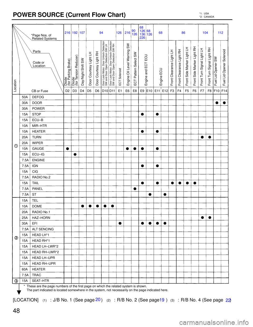
POWER SOURCE (Current Flow Chart)*1: USA
*2: CANADA
D2 D3F14
D5
D4 D6 E6 D10 E1 E11 F8 F10 F4 F6
E12
E10 F7 F3
94 126
68
126
90
126
11 2
216 68 68
126
136
226
104
86
107
D11 F5 E9
E8
Engine Oil Level W arning SW
Diode
(for Parking Brake)
Diode
(for Tension Reducer)
Door Courtesy Light LHDoor Lock Motor, Door Unlock Detection
SW and Door Open Detection SW LHDay/Night Shift SWECT SolenoidECT Pattern Select SW
Engine and ECT ECU
Front Turn Signal Light RH
Fuel Lid Opener SW
Fuel Lid Opener Solenoid
*Page Nos. of
Related Systems
Parts
Code or
Location
CB or Fuse
50A DEFOG
30A DOOR
30A POWER
15A STOP
15A ECU±B
10A MIR±HTR
10A HEATER
20A TURN
20A WIPER
10A GAUGE
15A ECU±IG
7.5A ENGINE
7.5A IGN
15A CIG
7.5A RADIO No.2
15A TAIL
7.5A PANEL
7.5A ST
15A TEL
10A DOME
20A RADIO No.1
25A HAZ±HORN
30A EFI
7.5A ALT SENCING
15A HEAD LH*1
15A HEAD RH*1
15A HEAD LH±LWR*2
15A HEAD RH±LWR*2
15A HEAD LH±UPR
15A HEAD RH±UPR
60A HEATER
7.5A TRAC
15A SEAT±HTR
Location
Door Courtesy Light RH
Door Lock Motor, Door Unlock Detection
SW and Door Open Detection SW RHEngine ECU
Front Turn Signal Light LH Front Side Marker Light RH Front Side Marker Light LH Front Clearance Light RH Front Clearance Light LH
192
216
�
* These are the page numbers of the first page on which the related system\
is shown.
The part indicated is located somewhere in the system, not necessarily o\
n the page indicated here.
[LOCATION](1): J/B No. 1 (See page 20)(2): R/B No. 2 (See page 19)(3): R/B No. 4 (See page 23)
20
19 22
WhereEverybodyKnowsYourName
Page 3996 of 4087
49
F16 F18 I1H8
G2
G1 H1 H3 H2 H4 H5 I2 I14 I15 L7 I16 L2 M2L6
L3 M4
80
194
111 94 101
62
68
101 11 2
126
186 154
162
68 68 94
216
90 86
107
H6 H7 H9 98
N1
Unlock Warning SW
[Ignition SW] Igniter No.1 Fuel Pump ECU
Glove Box Light
Headlight LH HI
Hazard SW
High Mount Stop Light
(w/ Rear Spailer) Horn LHISC ValveIgnition Key Cylinder Light
Key Inter Lock Solenoid
Moon Roof Control Relay Light Failure Sensor
Luggage Compartment
Light SW
A/T Indicator SW
Back±Up Light SW
Neutral Start SW Licence Plate Light Integration Relay Fuel Sender
Glove Box Light SW
Headlight RH HI
Headlight LH LO
Headlight RH LO
Horn RH
High Mount Stop Light
(w/o Rear Spailer)
Luggage Compartment
Light SW
Moon Roof Motor
86
98
108
182
216
82
91
94
102
82
216 90
104
(4)
: R/B No. 5 (See page ) 22
WhereEverybodyKnowsYourName