Page 1049 of 4087

SPEED SENSOR SIGNAL CHECK
1. Turn the ignition switch to OFF.
2. Using SST, connect terminals Ts and E1 of DLC1.SST 09843±18020
3. Start the engine.
4. Check that the ABS warning light blinks. HINT: If the ABS warning light does not blink, inspect the ABS
warning light circuit (see page BR±144).
5. Drive vehicle straight forward. HINT: Drive vehicle faster than 45 km/h (28 mph) for several
seconds.
6. Stop the vehicle.
7. Using SST, connect terminals Tc and E1 of DLC1.
SST 09843±18020
8. Read the number of blinks of the ABS warning light. HINT: See the list of diagnosis trouble codes shown on the
next page.
If every sensor is normal, a normal code is output (A cycle of
0.25 sec. on and 0.25 sec. OFF is repeated).
If 2 or more malfunction are indicated at the same time, the
lowest numbered code will be displayed 1st.
9. After performing the check, disconnect terminals Ts and E1,Tc and E1 of DLC1, and ignition switch turned off.
BR±80
±
BRAKE SYSTEM ANTI±LOCK BRAKE SYSTEM (ABS)
WhereEverybodyKnowsYourName
Page 1156 of 4087
LOCATION OF PLASTIC BODY PARTS
Outside Rear View Mirror (ABS)
Instrument Panel Safety Pad (PVC/PUR) Rear Spoiler (SMC)
Front Turn Signal Light (PC/PP)
Center Stop Light (PC)
Mead Light (PC/PP)
Head Light (PC/PP)
Front Bumper Extension
Mounting Bracket (PP)
Quarter Panel
Mud Guard (TPO)
Outside Moulding
Front Fender Mud Guard (TPO)
Front Spoiler (PUR) Cowl Top Ventilation Louver (PP)
Front Bumper Cover (PUR) Side Turn Signal Light (PMMA/ABS)
Cornering Light (PC)
HINT:
wResin material differs with model.
/ Made up of 2 or more kinds of materials.
PLASTIC BODY PARTSPP-4
WhereEverybodyKnowsYourName
Page 1284 of 4087
ELECTRONICALLY CONTROLLED HYDRAULIC COOLING FAN
Description
In this way system, the cooling fan ECU controls the hydraulic pressure ac\
ting on the hydraulic motor, thus
controlling the speed of the cooling fan steplessly in response to the c\
ondition of the engine and air conditioner.
Operation
The hydraulic pump is driven by a drive belt (V±ribbed belt). The sole\
noid valve adjusts the volume of oil
sent from the hydraulic pump to the hydraulic motor which drives the fan dir\
ectly, thereby controlling the fan
speed. Oil which has passed through the hydraulic motor is cooled by the oil coole\
r before returning to the reservoir
tank. The solenoid valve is controlled by the computer in accordance with the E/G\
rpm, water temp. and A/C
signals. CO±22
±
COOLIING SYSTEM Electronically Controlled Hydraulic
Cooling Fan (Description, Operation)
WhereEverybodyKnowsYourName
Page 2006 of 4087
FUEL SYSTEM
Fuel is pumped up by the fuel pump, which flows through the fuel filter unde\
r pressure through the fuel pipe
to the delivery pipe where it is distributed to each injector. The fuel pressure regulator adjusts the pressure of the fuel from the fuel \
line (high pressure side) to a pressure
284 kPa (2.9 kgf/cm2, 41 psi) higher than the pressure inside the intake \
manifold, and excess fuel is returned
to the fuel tank through the return pipe.
When the engine is hot, the fuel pressure is increased to control percolation in the fuel system and impr\
ove
restartability and idling stability.
The pulsation damper absorbs the slight fluctuations in fuel pressure ca\
used by the injector.
The injectors operate on input of injection signals from the ECU and inj\
ect fuel into the intake manifold.
FI±6
±
EFI SYSTEM Operation
WhereEverybodyKnowsYourName
Page 2007 of 4087

AIR INDUCTION SYSTEM
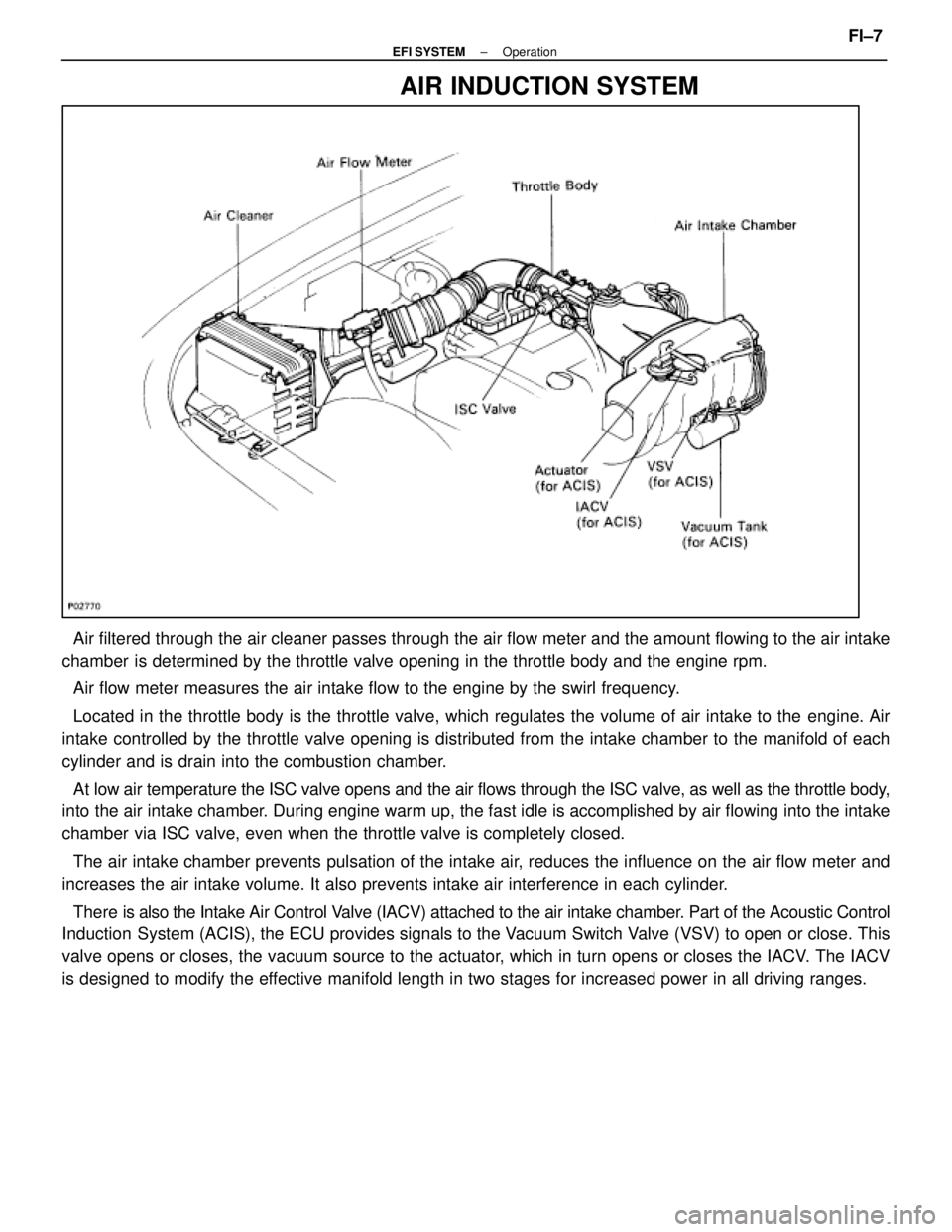
Air filtered through the air cleaner passes through the air flow meter a\
nd the amount flowing to the air intake
chamber is determined by the throttle valve opening in the throttle body and th\
e engine rpm.
Air flow meter measures the air intake flow to the engine by the swirl f\
requency.
Located in the throttle body is the throttle valve, which regulates the \
volume of air intake to the engine. Air
intake controlled by the throttle valve opening is distributed from the \
intake chamber to the manifold of each
cylinder and is drain into the combustion chamber.
At low air temperature the ISC valve opens and the air flows through the I\
SC valve, as well as the throttle body,
into the air intake chamber. During engine warm up, the fast idle is accomplished by air flowing into the intake
chamber via ISC valve, even when the throttle valve is completely closed.
The air intake chamber prevents pulsation of the intake air, reduces the influence on the air flow meter and
increases the air intake volume. It also prevents intake air interferenc\
e in each cylinder.
There is also the Int ake Air Control Valve (IACV) attached to the air intake chamber. Part of the Acoustic Control
Induction System (ACIS), the ECU provides signals to the Vacuum Switch Valve (VSV) to open or close. This
valve opens or closes, the vacuum source to the actuator, which in turn opens or closes the IACV. The IACV
is designed to modify the effective manifold length in two stages for increased power in all driving\
ranges.
±
EFI SYSTEM OperationFI±7
WhereEverybodyKnowsYourName
Page 2011 of 4087

FUEL SYSTEM
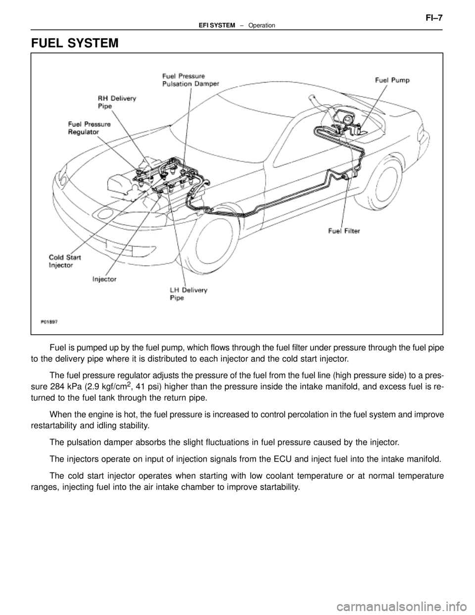
Fuel is pumped up by the fuel pump, which flows through the fuel filter under pr\
essure through the fuel pipe
to the delivery pipe where it is distributed to each injector and the cold\
start injector.
The fuel pressure regulator adjusts the pressure of the fuel from the fuel \
line (high pressure side) to a pres-
sure 284 kPa (2.9 kgf/cm
2, 41 psi) higher than the pressure inside the intake manifold, and exce\
ss fuel is re-
turned to the fuel tank through the return pipe.
When the engine is hot, the fuel pressure is increased to control percolatio\
n in the fuel system and improve
restartability and idling stability.
The pulsation damper absorbs the slight fluctuations in fuel pressure ca\
used by the injector.
The injectors operate on input of injection signals from the ECU and inj\
ect fuel into the intake manifold.
The cold start injector operates when starting with low coolant temperature or at normal temperature
ranges, injecting fuel into the air intake chamber to improve startability. FI±7
EFI SYSTEM
± Operation
WhereEverybodyKnowsYourName
Page 2170 of 4087

GENERAL MAINTENANCE
MA00M±03
There are the maintenance and inspection
items which are considered to be the owner's
responsibility. They can be performed by the
owner or be can have them done at a service
shop. These items include those which should
be checked on a daily basis, those which, in
most cases, do not require (special) tools and
those which are considered to be reasonable
for the owner to perform. Items and procedures
for general maintanance are as follows:
MA00P±04
OUTSIDE VEHICLE
1. TIRES
(a) Check the pressure with a gauge. Adjust ifnecessary.
(b) Check for cuts, damage or excessive wear.
2. WHEEL NUTS Wheel checking the tires, check the nuts for
looseness or for missing nuts. If necessary,
tighten them.
3. TIRE ROTATION It is recommended that tires be rotated every
12,000 km (7,500 miles).
4. WINDSHIELD WIPER BLADES Check for wear or cracks whenever they do not
wipe clean. Replace if necessary.
5. FLUID LEAKS
(a) Check underneath for leaking fuel, oil, water or
other fluid.
(b) If you smell gasoline fumes or notice any leak, have the cause found and corrected.
6. DOORS AND ENGINE HOOD
(a) Check that all doors including the trunk lid operate smoothly, and that all latches lock
securely.
(b) Check that the engine hood secondary latch secures the hood from opening when the
primary latch is released.
MA00R±05
INSIDE VEHICLE
7. LIGHTS
(a) C h e c k t h a t t h e h eadlights, stop lights,
tail±lights, turn signal lights, and other lights
are all working. (b) Check the headlight aiming.
8. WARNING LIGHT AND BUZZERS
Check that all warning lights and buzzers func-
tion properly.
9. HORN Check that it is working.
10. WINDSHIELD GLASS
Check for scratches, pits or abrasions.
11. WINDSHIELD WIPER AND WASHER
(a) Check operation of the wipers and washer.
(b) Check that the wipers do not streak.
12. WINDSHIELD DEFROSTER Check that the air comes out from the defroster
outlet when operating the heater air condition-
er at defroster mode.
13. REAR VIEW MIRROR
Check that it is mounted securely.
14. SUN VISORS Check that they move freely and are mounted
securely.
15. STEERING WHEEL Check that it has the specified freeplay. Be
alert for changes in steering condition, such as
hard steering, excessive freeplay or strange
noise.
16. SEATS
(a) Check that all front seat controls such as seat adjusters, seatback recliner, etc. operate
smoothly.
(b) Check that all latches lock securely in any position.
(c) Check that the locks hold securely in any latched position.
(d) Check that the head restraints move up and
down smoothly and that the locks hold securely
in ay latches position.
(e) For folding±down rear seat backs, check that the latches lock securely.
17. SEAT BELTS
(a) Ch e ck th a t th e se a t be lt syste m su ch as buckles, retractors and anchors operate
properly and smoothly.
(b) Check that the belt webbing is not cut, frayed,
worn or damaged.
18. ACCELERATOR PEDAL Check the pedal for smooth operation and un-
even pedal effort or catching.
±
MAINTENANCE (1UZ ± FE)MA±19
WhereEverybodyKnowsYourName
Page 2391 of 4087

FUEL SYSTEM
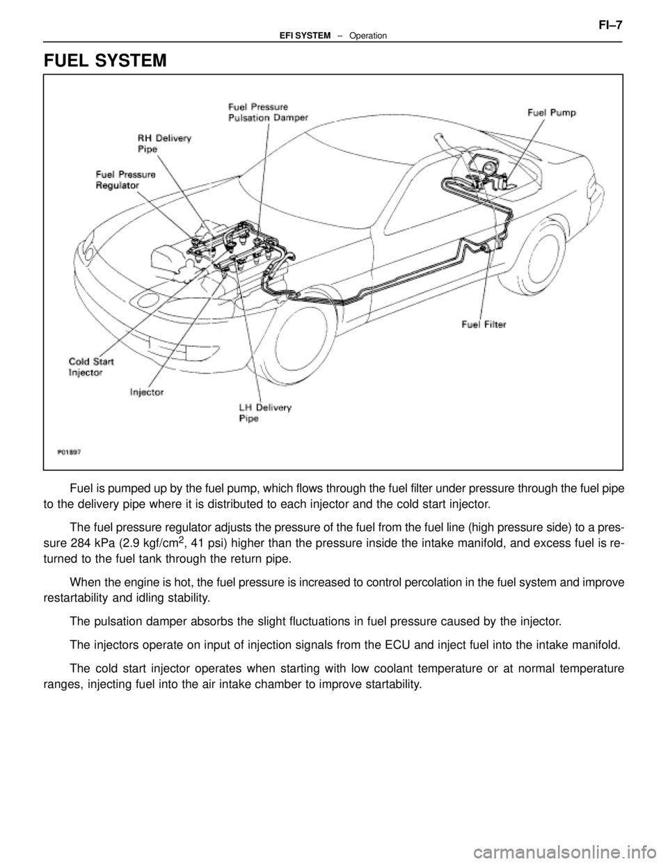
Fuel is pumped up by the fuel pump, which flows through the fuel filter under pr\
essure through the fuel pipe
to the delivery pipe where it is distributed to each injector and the cold\
start injector.
The fuel pressure regulator adjusts the pressure of the fuel from the fuel \
line (high pressure side) to a pres-
sure 284 kPa (2.9 kgf/cm
2, 41 psi) higher than the pressure inside the intake manifold, and exce\
ss fuel is re-
turned to the fuel tank through the return pipe.
When the engine is hot, the fuel pressure is increased to control percolatio\
n in the fuel system and improve
restartability and idling stability.
The pulsation damper absorbs the slight fluctuations in fuel pressure ca\
used by the injector.
The injectors operate on input of injection signals from the ECU and inj\
ect fuel into the intake manifold.
The cold start injector operates when starting with low coolant temperature or at normal temperature
ranges, injecting fuel into the air intake chamber to improve startability. FI±7
EFI SYSTEM
± Operation
WhereEverybodyKnowsYourName