Page 677 of 4087

WIRING DIAGRAM
Position sensor check.OK
Proceed to next circuit inspection
shown on matrix chart (See page
BE±276).
NG
Check position sensor. NG
OK NG
OK Replace position sensor.
Repair or replace harness or
connector.
Check harness and connectors between
ECU and position sensors. (See page
IN±27).
Check and replace ECU.
Position Sensor Circuit
CIRCUIT DESCRIPTION
The position sensor senses movement of the seat and send
pulse signals to the ECU. The position sensor sends pulses
to the ECU in proportion to the amount of seat movement, as
shown in the diagram on the left.
The ECU uses the number of pulses to constantly calculate
the position relative to the memory position and returns the
seat to the memorized position.
If a malfunction occurs in a position sensor and a sensor sig-
nal is not input to the ECU even when the motor operates, the
ECU prohibits return operation.
DIAGNOSTIC CHARTDIAGNOSTIC CHART
BE±294±
BODY ELECTRICAL SYSTEM Power Seat Control System (Driver's Seat)
WhereEverybodyKnowsYourName
Page 681 of 4087
Check stop light operation.NG
OK OK
NG Check stop light circuit
(See page
BE±64).
Proceed to next circuit inspection
shown on matrix chart
(See page
BE±276).
Check voltage between terminals STOP
of ECU connector and body ground.
Check and repair harness and connec-
tor between ECU and stop light switch.
WIRING DIAGRAM
Stop Light Circuit
CIRCUIT DESCRIPTION
The stop light switch sends a brake ON of Off signal to the ECU. When the ECU receives a brake ON signal
it prohibits return of the seat.
DIAGNOSTIC CHARTDIAGNOSTIC CHART
BE±298±
BODY ELECTRICAL SYSTEM Power Seat Control System (Driver's Seat)
WhereEverybodyKnowsYourName
Page 683 of 4087
WIRING DIAGRAM
Check shift position indicator. NGOK
OK
NG Check shift position indicator
circuit (See page BE± 141).
Check voltage between terminal P of ECU
connector and body ground. Proceed to next circuit inspection
shown on matrix chart (See page
BE±276
).
Check and repair harness and connector
between ECU and connector.
Neutral Start Switch Circuit
CIRCUIT DESCRIPTION
The neutral start switch detects when the shift position is in P range and \
sends a signal to the ECU.
When the return switch is turned ON with the IG SW ON and the shift in P\
range, the ECU performs
return operation.
DIAGNOSTIC CHARTDIAGNOSTIC CHART
BE±300±
BODY ELECTRICAL SYSTEM Power Seat Control System (Driver's Seat)
WhereEverybodyKnowsYourName
Page 687 of 4087
WIRING DIAGRAM
Check voltage between each termi-
nal and a SGND of ECU connector.OK
NG NG
NG
OK
OK
Check power seat switch.
Replace power seat switch.Proceed to next circuit inspection
shown on matrix chart (See page
BE±276).
Check harness and connectors between
ECU and power seat switch (See page
IN±27).Repair or replace harness
or connector.
Check and replace ECU.
Power Seat Switch Circuit
CIRCUIT DESCRIPTION
When the power seat switch is operated, a signal is sent from the power seat\
switch to the ECU and the ECU
sends a signal to the motor to make it operate (except for the lumbar s\
upport).
Even if a malfunction should occur with the position sensor and return opera\
tion is prohibited, manual operation
will occur as normal.
DIAGNOSTIC CHARTDIAGNOSTIC CHART
BE±304±
BODY ELECTRICAL SYSTEM Power Seat Control System (Driver's Seat)
WhereEverybodyKnowsYourName
Page 689 of 4087

WIRING DIAGRAM
Check harness and connector between
ECU and tilt & telescopic ECU (See page
IN±27). NG
NG
OK
OK
Check return operation of tilt and
telescopic ECU, and mirror ECU. Repair or replace harness or
connector.
Check and replace tilt &
telescopic ECU.
Proceed to next circuit inspection shown on
matrix chart (See page BE±276).
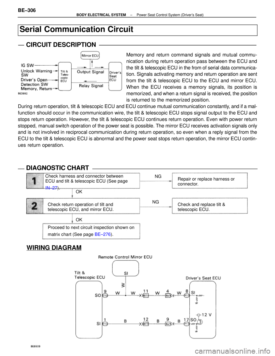
Serial Communication Circuit
CIRCUIT DESCRIPTION
Memory and return command signals and mutual commu-
nication during return operation pass between the ECU and
the tilt & telescopic ECU in the from of serial data communica-
tion. Signals activating memory and return operation are sent
from the tilt & telescopic ECU to the ECU and mirror ECU.
When the ECU receives a memory signals, its position is
memorized, and when a return signal is received, the position
is returned to the memorized position.
During return operation, tilt & telescopic ECU and ECU continue mutual communi\
cation constantly, and if a mal-
function should occur in the communication wire, the tilt & telescopic ECU stops signal output to the ECU and
stops return operation. However, the tilt & telescopic ECU continues return operation. Even with power \
return
stopped, manual switch operation of the power seat is possible. The mirror ECU receives activation signals only
and is not involved in reciprocal communication during return operation, so\
even when a reply signal from the
ECU to the tilt & telescopic ECU is abnormal and the power seat stops retur\
n operation, the mirror ECU contin-
ues return operation.
DIAGNOSTIC CHARTDIAGNOSTIC CHART
BE±306±
BODY ELECTRICAL SYSTEM Power Seat Control System (Driver's Seat)
WhereEverybodyKnowsYourName
Page 693 of 4087

�������� ��������
Parts Name������������������\
����������� ������������������\
�����������Function
�������� �
�������
��������
Passenger's Seat
ECU������������������\
����������� �
������������������\
����������
������������������\
�����������
The passenger seat ECU controls the distance the seat slides when the po\
wer seat switch is
operated and also controls the power slide distance during return operat\
ion.
�������� �
�������
��������Power Seat Switch������������������\
����������� �
������������������\
����������
������������������\
�����������
When the power seat switch is operated, a seat slide signal is sent to t\
he ECU. The reclining
slide of the switch is linked directly to the motor operation.
�������� �
�������
��������Slide Position Sensor������������������\
����������� �
������������������\
����������
������������������\
�����������
The slide position sensor detects the slide distance during walk±in o\
peration and
inputs the information to the ECU.
�������� �
�������
��������
Slide Neutral Limit
Switch������������������\
����������� �
������������������\
����������
������������������\
�����������
This switch detects the neutral position of the seat slide and input the\
information to the ECU.
�������� �
�������
��������
Reclining Front Limit
Switch������������������\
����������� �
������������������\
����������
������������������\
�����������
This switch detects when the seatback is inclined fully forward and info\
rms the
ECU.
�������� �
�������
��������
Reclining Rear Limit
Switch������������������\
����������� �
������������������\
����������
������������������\
�����������
This switch detects when the seatback is pulled back and informs the ECU\
.
�������� ��������Motor������������������\
����������� ������������������\
�����������There are two motors, one each for seat sliding and for reclining.
�������� �
�������
��������
Tension Reducer and
Buckle Switch������������������\
����������� �
������������������\
����������
������������������\
�����������
This switch inputs a signal to the ECU to inform it whether the tongue o\
f the
passenger's seat belt is inserted in the buckle.
±
BODY ELECTRICAL SYSTEM Power Seat Control System (Passenger's Seat)BE±311
WhereEverybodyKnowsYourName
Page 711 of 4087
WIRING DIAGRAM
Position Sensor Circuit
CIRCUIT DESCRIPTION
The position sensor senses movement of the seat and send
pulse signals to the ECU. The position sensor sends pulses
to the ECU in proportion to the amount of seat movement, as
shown in the diagram on the left.
If a malfunction occurs in a position sensor and a sensor sig-
nal is not input to the ECU even when the motor operates, the
ECU prohibits return operation.
DIAGNOSTIC CHARTDIAGNOSTIC CHART
Inspect the circuit which is malfunctioning.
Position sensor check.OK
NG
OK
OK NG
NG Proceed to next circuit inspection
shown on matrix chart (See page
BE±319
)
Replace position sensor.
Check position sensor.
Check harness and connectors between
ECU and position sensor (See page IN±27). Repair or replace harness or
connector.
Check and replace ECU.
BE±330±
BODY ELECTRICAL SYSTEM Power Seat Control System (Passenger's Seat)
WhereEverybodyKnowsYourName
Page 788 of 4087

WIRING DIAGRAM
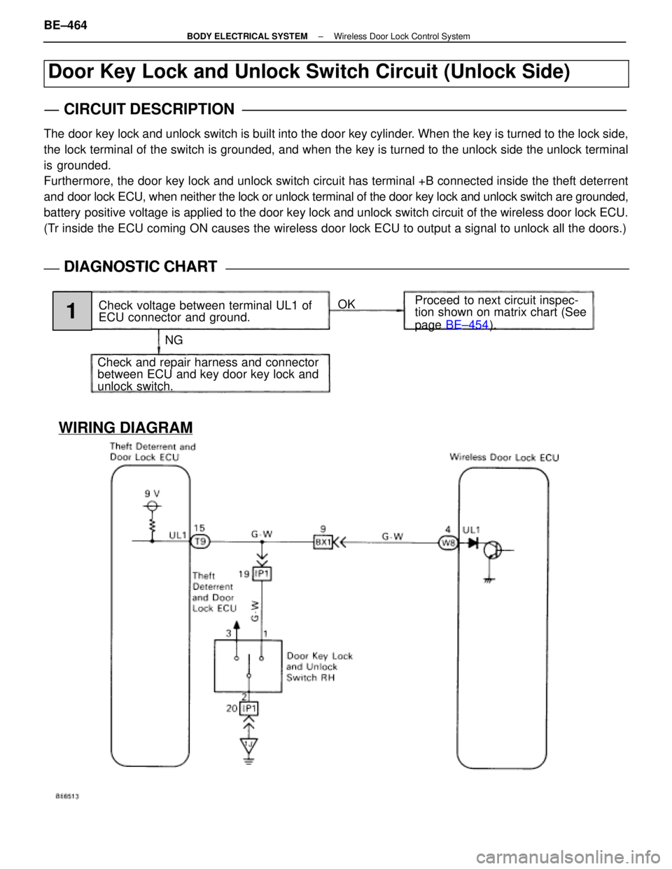
Door Key Lock and Unlock Switch Circuit (Unlock Side)
CIRCUIT DESCRIPTION
The door key lock and unlock switch is built into the door key cylinder. When the key is turned to the lock side,
the lock terminal of the switch is grounded, and when the key is turned to the unlock side the unlock terminal
is grounded.
Furthermore, the door key lock and unlock switch circuit has terminal +B\
connected inside the theft deterrent
and door lock ECU, when neither the lock or unlock terminal of the door key\
lock and unlock switch are grounded,
battery positive voltage is applied to the door key lock and unlock switch circuit of the wireless d\
oor lock ECU.
(Tr inside the ECU coming ON causes the wireless door lock ECU to output a \
signal to unlock all the doors.)
DIAGNOSTIC CHARTDIAGNOSTIC CHART
NGOK
Proceed to next circuit inspec-
tion shown on matrix chart (See
page
BE±454 ).
Check voltage between terminal UL1 of
ECU connector and ground.
Check and repair harness and connector
between ECU and key door key lock and
unlock switch.
1
BE±464±
BODY ELECTRICAL SYSTEM Wireless Door Lock Control System
WhereEverybodyKnowsYourName