Page 864 of 4087
(TURN SIGNAL AND HAZARD WARNING
LIGHT SYSTEM)
Description ± TURN SIGNAL AND
HAZARD WARNING LIGHT SYSTEM
The component parts of this system and their function are as shown in the f\
ollowing table.
Parts NameFunction
Turn Signal SwitchSwitches current from the turn signal flasher to the left side or right \
side.
Hazard Warning
SwitchModifies the circuit to the flasher relay and turn signal switch in acco\
rdance with the
respective switch positions.
Turn Signal FlasherReceives current from the hazard warning switch and flashes the turn sig\
nal lights by
switching the current to the lights ON and OFF.
PARTS LOCATION ± TURN SIGNAL
±
BODY ELECTRICAL SYSTEM Lighting SystemBE±65
WhereEverybodyKnowsYourName
Page 865 of 4087
WIRING AND CONNECTOR DIAGRAMS
Turn Signal and Hazard Warning Lights
BE±66±
BODY ELECTRICAL SYSTEM Lighting System
WhereEverybodyKnowsYourName
Page 866 of 4087
Parts Replacement (Turn Signals)
(Cornering Light)
REPLACEMENT OF CORNARING LIGHT
1. REMOVE CORNARING LIGHT(a) Disconnect negative (±) terminal from the battery.
CAUTION: Work must be started after approx. 20 se-
conds or longer from the time the ignition switch is
turned to the ºLOCKº position and negative (±) terminal
cable is disconnected from the battery.
(b) Remove front under cover. (See page BO±92 )
(c) Remove a screw and two nuts.
(d) Remove cornaring light from bumper.
(e) Disconnect connector.
2. INSTALL CORNARING LIGHT For installation follow the removal procedure in reverse.
(Front Turn Signal Light)
REPLACEMENT OF FRONT TURN
SIGNAL LIGHT
(See page BE±37 )
HINT: Replacement of Headlight (LO±Beam)
(Rear Combination Light)
(See page BE±56 )
±
BODY ELECTRICAL SYSTEM Lighting SystemBE±67
WhereEverybodyKnowsYourName
Page 867 of 4087

Parts Inspection (Turn and Hazard)
(Combination Switch Assembly)
(See page BE±39)
HINT: Inspect turn signal light switch.
(Turn Signal Flasher)
REMOVAL AND INSTALLATION OF TURN
SIGNAL FLASHER
(See page BE±16 )
INSPECTION OF TURN SIGNAL
FLASHER
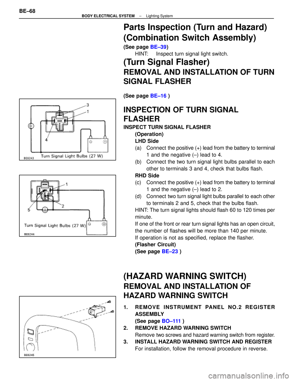
INSPECT TURN SIGNAL FLASHER
(Operation)
LHD Side
(a) Connect the positive (+) lead from the battery to terminal
1 and the negative (±) lead to 4.
(b) Connect the two turn signal light bulbs parallel to each other to terminals 3 and 4, check that bulbs flash.
RHD Side
(c) Connect the positive (+) lead from the battery to terminal
1 and the negative (±) lead to 2.
(d) Connect two turn signal light bulbs parallel to each other
to terminals 2 and 5, check that the bulbs flash.
HINT: The turn signal lights should flash 60 to 120 times per
minute.
If one of the front or rear turn signal lights has an open circuit,
the number of flashes will be more than 140 per minute.
If operation is not as specified, replace the flasher.
(Flasher Circuit)
(See page BE±23 )
(HAZARD WARNING SWITCH)
REMOVAL AND INSTALLATION OF
HAZARD WARNING SWITCH
1. REMOVE INSTRUMENT PANEL NO.2 REGISTER
ASSEMBLY
(See page BO±111 )
2. REMOVE HAZARD WARNING SWITCH Remove two screws and hazard warning switch from register.
3. INSTALL HAZARD WARNING SWITCH AND REGISTER
For installation, follow the removal procedure in reverse.
BE±68
±
BODY ELECTRICAL SYSTEM Lighting System
WhereEverybodyKnowsYourName
Page 869 of 4087

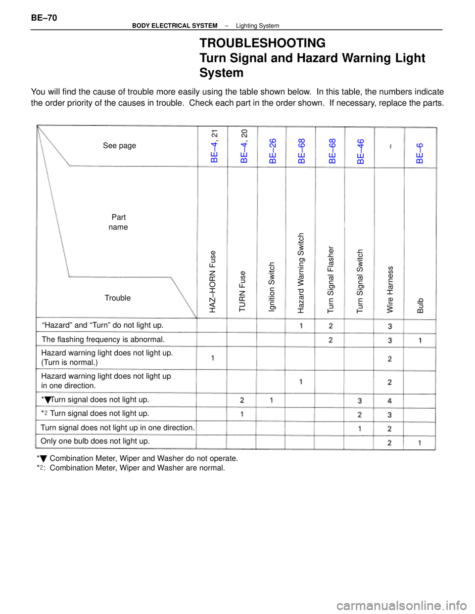
TROUBLESHOOTING
Turn Signal and Hazard Warning Light
System
You will find the cause of trouble more easily using the table shown below. In this table, the numbers indicate
the order priority of the causes in trouble. Check each part in the order \
shown. If necessary, replace the parts.
See pagePart
name
Trouble
ªHazardº and ªTurnº do not light up.
The flashing frequency is abnormal.
Hazard warning light does not light up.
(Turn is normal.)
Hazard warning light does not light up
in one direction.
* � Turn signal does not light up.
*
� Turn signal does not light up.
Turn signal does not light up in one direction.
Only one bulb does not light up.
* � : Combination Meter, Wiper and Washer do not operate.
* � : Combination Meter, Wiper and Washer are normal.
HAZ±HORN Fuse
TURN Fuse
Ignition Switch
Hazard Warning Switch
Turn Signal Flasher
Turn Signal Switch
Wire Harness
Bulb
BE±4
, 21
BE±4
, 20
BE±26
BE±68
BE±68
BE±46
BE±6
BE±70±
BODY ELECTRICAL SYSTEM Lighting System
WhereEverybodyKnowsYourName
Page 893 of 4087

TROUBLESHOOTING
You will find the cause of trouble more easily by properly using the table \
shown below. In this table, the num-
bers indicate the order priority of causes of trouble. Check each part in th\
e order shown. If necessary, re-
place the parts.
See pageB±4,21BE±26BE±4,20BE±91BE±90BE±92BE±91BE±93±
Trouble
Part Name
AM1 FuseIgnition SwitchWIPER FuseWiper SwitchWiper MotorWasher MotorWasher SwitchWasher Hose and NozzleWire Harness
Wipers and washers do not operate.*1132456
Wipers and washers do not operate.*221345
Wipers and washers do not operate.*31234
Wipers do not operate in LO, HI or MIST.123
Wipers do not operate in INT.123
Washer motor does not operate.213
Wipers do not operate when washer switch
is ON.12
Washer fluid does not spray.1
*1: Door Lock and Power Windows do not operate
*
2: Door Lock and Power Window are normal. Combination Meter and Turn Signal do not operate.
*
3: Combination Meter and Turn Signal are normal.
BE±94
±
BODY ELECTRICAL SYSTEM Wiper and Washer System
WhereEverybodyKnowsYourName
Page 907 of 4087

ConnectionCheck forTester connectionConditionSpecified value
Turn signalHazard warning switch ONBattery positiveTurn signal
SW andB 16 Ground
Hazard warning switch ONBattery ositive
voltage e 0V
HazardB±16±Ground
IG SW ON and turn signal SW ºLeftºBattery positive
Warning
Si hVoltage
IG SW ON and turn signal SW ºLeftºBattery ositive
voltage e 0V
SwitchVoltage
Hazard warning switch ONBattery positive
B 17 Ground
Hazard warning switch ONBattery ositive
voltage e 0VB±17±Ground
IG SW ON and turn signal SW ºRightºBattery positiveIG SW ON and turn signal SW ºRightºBattery ositive
voltage e 0V
HeadlightLi ht t l SWDimmer SW ºHIº orBattery positiveHeadlight
VoltageB7±GroundLight control SW
ºHEADº
Dimmer SW HI or
ºFlashº
Battery ositive
voltageVoltageB7±GroundºHEADºDimmer SW ºLOºNo voltage
ContinuityB6±GroundLight control SW
º
HEADº
Dimmer SW ºHIº or
ºFlashºContinuityContinuityB6 GroundºHEADºDimmer SW ºLOºNo continuity
IgniterVoltageA9±GroundEngine RunningVoltage
fluctuates
ECT patternVoltageB4 GroundIG SW ON and ECT patternPWRBattery positive voltageECT attern
Select switchVoltageB4±GroundIG SW ON and ECT attern
select SW positionNORMNo voltage
Engine oilOil temperature below approx. 55 5C (131 5F)Continuityg
Level warn-
ing Switch
ContinuityB8±Ground
Oil temperature
above approx. 55 5CON (float up)ContinuitygContinuityB8 Groundabove a rox. 55 C
(131 5F) and SW
positionOFF (float off)No continuity
GAUGE fuseVoltageA1 GroundIgnition switchONBattery positive voltageVoltageA1±GroundIgnition switch
positionLOCK, ACC, STARTNo voltage
Neutral StartVoltageA12±GroundIgnition switch
position
START (ºPº or ºNº
range)Battery positive voltage
switch
VoltageA12 GroundpositionLOCK, ACC, ONNo voltage
ECU±BVoltageC11 GroundIgnition switchONBattery positive voltage
FuseVoltageC11±GroundIgnition switch
positionLOCK, ACC, STARTNo voltage
Rheostat
Li ht t l
ON (Rheostat knob
t d itiBtt ltLight control
VolumeLight control SWturned any position
except fully clock-
Battery voltage or
5V or moreVolume
VoltageA2±Ground
g
HEAD or TAIL and
rheostat volume
except fully clock-
wise)5V or more
VoltageA2 Groundrheostat volume
knob positionOFF (Rheostat knob)
turned fully clockNo voltageknob ositionturned fully clock-
wise)No voltage
GroundA8±GroundConstantContinuity
ContinuityA10±GroundConstantContinuityContinuityA22±GroundConstantContinuity
A23±GroundConstantContinuity
*1 Jack up the vehicle.*2 Shift lever position is ºPº range.
If circuit is not as specified, refer to BE±100 wiring diagrams
and inspect the circuits connected to other parts.
BE±108
±
BODY ELECTRICAL SYSTEM Combination Meter
WhereEverybodyKnowsYourName
Page 935 of 4087

WIRING DIAGRAM
DTC25, 26, 27TRAC Sub±Throttle Valve
CIRCUIT DESCRIPTION
DTC No.DTC Detecting ConditionTrouble Area
25
The difference between the sub±throttle sensor signal
voltage and the voltage required by the step count is 1
V or more.
Sub±throttle actuator.
Throttle body (sub±throttle valve is truck or operation is
faulty).
Sub±throttle position sensor.
Open or short in sub±throttle position sensor circuit.
ECM
TRAC ECU
26
Even when sub±throttle valve is driven to the fully open
position, input voltage at terminal VSH does not come
within range of the specifications 3 ~ 4.5 V.
Sub±throttle actuator.
Throttle body (sub±throttle valve is truck or operation is
faulty).
Sub±throttle position sensor.
Open or short in sub±throttle position sensor circuit.
ECM
TRAC ECU
27When input voltage at ECU terminal VSH is less than
the specification by about 2.5 V for 0.2 sec. or more.
Sub±throttle actuator (return spring is disconnected).
Sub±throttle position sensor.
Open or short in sub±throttle position sensor circuit.
ECM
TRAC ECU
C
OK
Hint
PRemove air cleaner and duct.
Open and close the sub±throttle valve manually and
check the condition during operation.
The valve should operate smoothly without catch-
ing.
If sub±throttle actuator, sub±throttle valve, sub±throttle
position sensor and harness are free from any defect,
ECM may be defective. If ECM is free from any defect,
TRAC ECU may be defective.
±
BRAKE SYSTEM TRACTION CONTROL SYSTEM (TRAC)BR±189
WhereEverybodyKnowsYourName