Page 2808 of 4087
ELECTRONICALLY CONTROLLED HYDRAULIC COOLING FAN
Description
In this way system, the cooling fan ECU controls the hydraulic pressure ac\
ting on the hydraulic motor, thus
controlling the speed of the cooling fan steplessly in response to the c\
ondition of the engine and air conditioner.
Operation
The hydraulic pump is driven by a drive belt (V±ribbed belt). The sole\
noid valve adjusts the volume of oil
sent from the hydraulic pump to the hydraulic motor which drives the fan dir\
ectly, thereby controlling the fan
speed. Oil which has passed through the hydraulic motor is cooled by the oil coole\
r before returning to the reservoir
tank. The solenoid valve is controlled by the computer in accordance with the E/G\
rpm, water temp. and A/C
signals. CO±22
±
COOLIING SYSTEM Electronically Controlled Hydraulic
Cooling Fan (Description, Operation)
WhereEverybodyKnowsYourName
Page 2950 of 4087
SR±52).
IN±33).
WIRING DIAGRAM
Memory & Return Switches Circuit
CIRCUIT DESCRIPTION
A memory command signal when switch 1 or 2 pushed while SET
switch is being pushed ON or a return command signal when
switch 1 or 2 is pushed ON is sent to the ECU for memory and re-
turn operations of the tilt, telescopic, seat and mirror.
DIAGNOSTIC CHARTDIAGNOSTIC CHART
SR±90±
STEERING STEERING COLUMN
WhereEverybodyKnowsYourName
Page 2957 of 4087

OKNG
NGOK
NGOK
OKNG
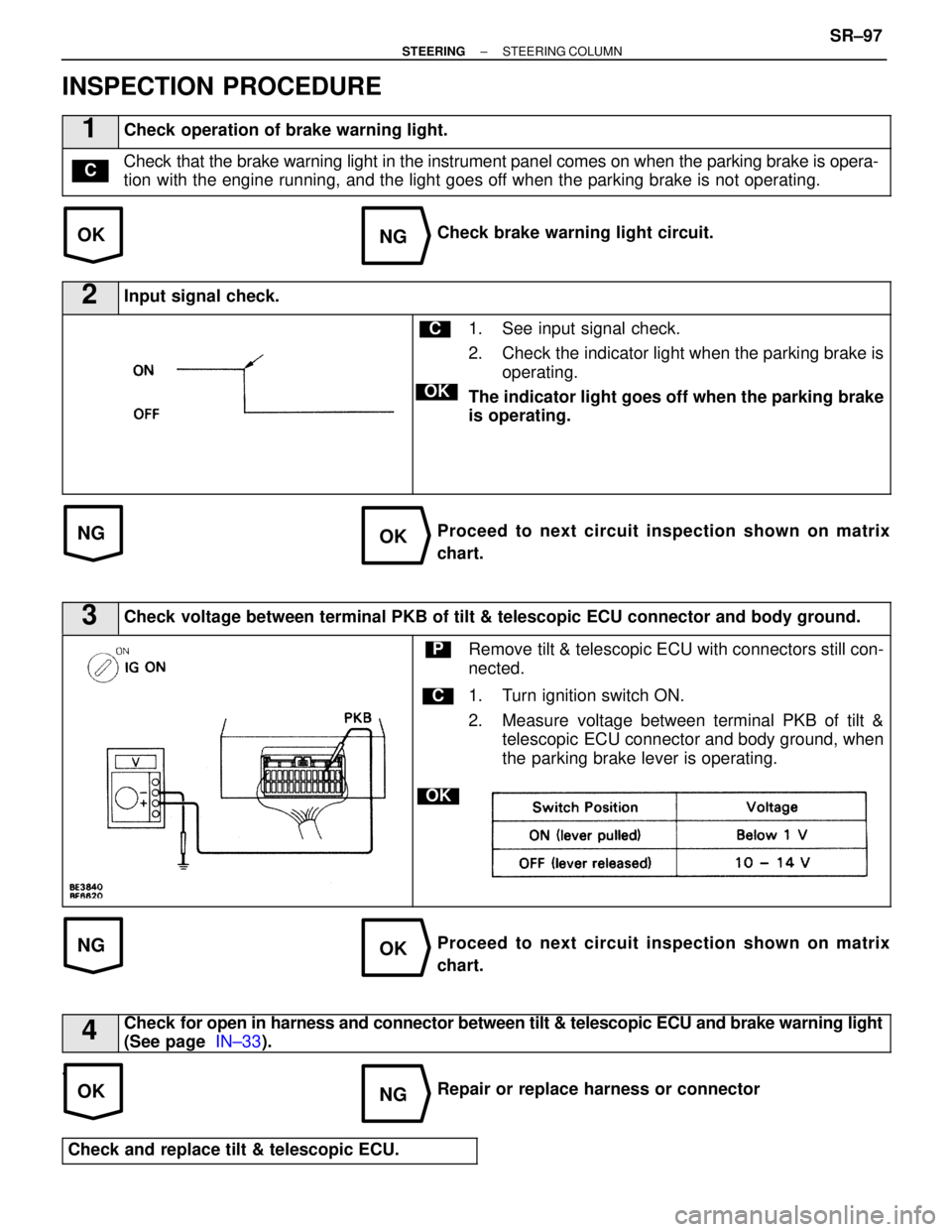
INSPECTION PROCEDURE
1Check operation of brake warning light.
Check that the brake warning light in the instrument panel comes on when the \
parking brake is opera-
tion with the engine running, and the light goes off when the parking brake is not operating.C
Check brake warning light circuit.
2Input signal check.
C
OK
1. See input signal check.
2. Check the indicator light when the parking brake isoperating.
The indicator light goes off when the parking brake
is operating.
Proceed to next circuit inspection shown on matrix
chart.
3Check voltage between terminal PKB of tilt & telescopic ECU connector and bod\
y ground.
C
OK
PRemove tilt & telescopic ECU with connectors still con-
nected.
1. Turn ignition switch ON.
2. Measure voltage between terminal PKB of tilt & telescopic ECU connector and body ground, when
the parking brake lever is operating.
Proceed to next circuit inspection shown on matrix
chart.
4Check for open in harness and connector between tilt & telescopic ECU and brak\
e warning light
(See page IN±33).
.
Repair or replace harness or connector
Check and replace tilt & telescopic ECU.
±
STEERING STEERING COLUMNSR±97
WhereEverybodyKnowsYourName
Page 3037 of 4087
5. REMOVE TURN SIGNAL BRACKET
6. REMOVE PROTECTOR
7. REMOVE CONNECTOR BRACKET
8. REMOVE TELESCOPIC LEVER SERRATIONATTACHMENT
Remove the nut and the serration attachment.
9. REMOVE TELESCOPIC LEVER
(a) Remove the bolt, collar, lever and washer.
(b) Remove the ball and compression spring.
±
STEERING STEERING COLUMNSR±15
WhereEverybodyKnowsYourName
Page 3047 of 4087
19. INSTALL CONNECTOR BRACKET
Torque: 4.9 NVm (50 kgf Vcm, 43 in. Vlbf)
20. INSTALL PROTECTOR
21. INSTALL TURN SIGNAL BRACKET
Install the turn signal bracket so that its upper surface is par-
allel with upper surface of the capsule of the breakaway
bracket.
22. INSTALL UPPER BRACKET
(a) Install the upper bracket with 2 new tapered±head bolts.
(b) Tighten the 2 tapered±head bolts until the bolt heads break off.
23. INSTALL LOWER DUST COVER
(a) Using a press, install the dust seal.
±
STEERING STEERING COLUMNSR±25
WhereEverybodyKnowsYourName
Page 3052 of 4087
6. REMOVE TURN SIGNAL BRACKET
7. REMOVE NO. 1 PROTECTOR AND NO. 2 PROTECTOR
8. REMOVE CONNECTOR BRACKET
9. REMOVE UPPER BRACKET
(a) U s i n g a c e n t e r i n g p u n c h , m a r k t h e c e n t e r o f t h e 2tapered±head bolts.
(b) U s i n g a 4 ± 5 m m ( 0 . 16±0.20 in.) drill, drill into the 2
tapered±head bolts.
(c) Using a screw extractor, remove the 2 tapered±head bolts.
(d) Remove the bracket and column upper camp.
SR±30
±
STEERING STEERING COLUMN
WhereEverybodyKnowsYourName
Page 3058 of 4087
6. INSTALL UPPER BRACKET
(a) Install the upper bracket with 2 new tapered±head bolts.
(b) Tighten the tapered±head bolts until the bolt heads break off.
7. INSTALL CONNECTOR BRACKET
Torque: 4.9 N Vm (50 kgf Vcm, 43 in. Vlbf)
8. INSTALL NO. 1 PROTECTOR AND NO. 2 PROTECTOR
9. INSTALL TURN SIGNAL BRACKET
Install the turn signal bracket so that its upper surface is par-
allel with upper surface of the capsule of the breakaway
bracket.
10. INSTALL TILT AND TELESCOPIC POSITION SENSORS
SR±36
±
STEERING STEERING COLUMN
WhereEverybodyKnowsYourName
Page 3062 of 4087

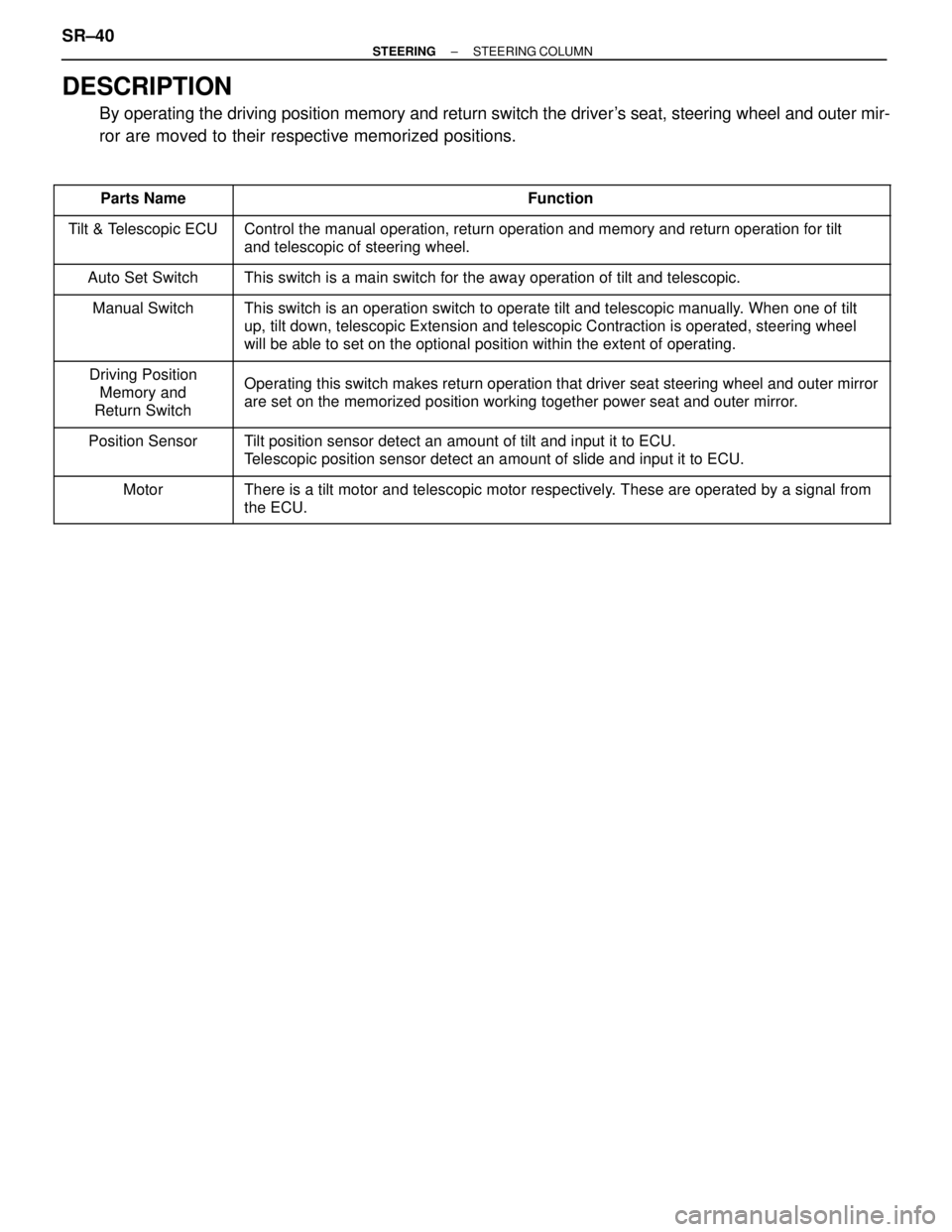
DESCRIPTION
By operating the driving position memory and return switch the driver's seat, steering wheel and outer mir-
ror are moved to their respective memorized positions.
�������� �
�������
��������Parts Name������������������\
����������� �
������������������\
����������
������������������\
�����������Function�������� �
�������
�
�������
��������
Tilt & Telescopic ECU
������������������\
����������� �
������������������\
����������
�
������������������\
����������
������������������\
�����������
Control the manual operation, return operation and memory and return ope\
ration for tilt
and telescopic of steering wheel.
�������� ��������Auto Set Switch������������������\
����������� ������������������\
�����������This switch is a main switch for the away operation of tilt and telescop\
ic.
�������� �
�������
�
�������
��������
Manual Switch������������������\
����������� �
������������������\
����������
�
������������������\
����������
������������������\
�����������
This switch is an operation switch to operate tilt and telescopic manual\
ly. When one of tilt
up, tilt down, telescopic Extension and telescopic Contraction is operat\
ed, steering wheel
will be able to set on the optional position within the extent of operat\
ing.
�������� �
�������
��������
Driving Position
Memory and
Return Switch������������������\
����������� �
������������������\
����������
������������������\
�����������
Operating this switch makes return operation that driver seat steering w\
heel and outer mirror
are set on the memorized position working together power seat and outer \
mirror.
�������� �
�������
��������Position Sensor
������������������\
����������� �
������������������\
����������
������������������\
�����������Tilt position sensor detect an amount of tilt and input it to ECU.
Telescopic position sensor detect an amount of slide and input it to ECU.\
�������� �
�������
��������Motor
������������������\
����������� �
������������������\
����������
������������������\
�����������There is a tilt motor and telescopic motor respectively. These are operated by a signal from
the ECU.
SR±40±
STEERING STEERING COLUMN
WhereEverybodyKnowsYourName