Page 2585 of 4087
15. DISCONNECT HOSESDisconnect the following hoses:(1) Water by±pass hose (from water inlet housing) from ISC valve
(2) Vacuum hose (from PS air control valve) from air in-
take chamber
(3) Vacuum sensing hose (from fuel pressure regula- tor) from vacuum pipe
(4) Two vacuum hoses (from VSV for EVAP system) from vacuum pipe
(5) Vacuum hose (from charcoal canister) from vacu- um pipe.
(6) Water by±pass hose (from EGR valve) from water by±pass pipe
(7) Vacuum hose (from brake booster) from air intake chamber
(8) Vacuum hose (from VSV for heater water valve)
from air intake chamber
(9) PCV hose from LH cylinder head cover
16. REMOVE AIR INTAKE CHAMBER (a) Remove the bolt, stud bolt and accelerator bracket.
ST±10
±
STARTING SYSTEM Starter
WhereEverybodyKnowsYourName
Page 2604 of 4087
(e) Tighten the bolt holding the EGR pipe to the air intakechamber.
Torque: 18 N Vm (185 kgf Vcm, 13 ft Vlbf)
(f) Tighten the bolt holding the EGR pipe to the RH cylinder
head.
Torque: 18 N Vm (185 kgf Vcm, 13 ft Vlbf)
(g) Connect the cold start injector tube to the RH delivery
pipe with two new gaskets and union bolt.
Torque: 15 N Vm (150 kgf Vcm, 11 ft Vlbf)
(h) Install the accelerator bracket with the bolt and stud bolt.
13. CONNECT HOSES Connect the following hoses:(1) Water by±pass (from EGR valve) to water bypass
pipe
(2) Vacuum hose (from brake booster) to air intake chamber
(3) Vacuum hose (from VSV for heater water valve) to
air intake chamber
(4) PCV hose to LH cylinder head cover
±
STARTING SYSTEM StarterST±29
WhereEverybodyKnowsYourName
Page 2900 of 4087
15. DISCONNECT HOSESDisconnect the following hoses:(1) Water by±pass hose (from water inlet housing) from ISC valve
(2) Vacuum hose (from PS air control valve) from air in-
take chamber
(3) Vacuum sensing hose (from fuel pressure regula- tor) from vacuum pipe
(4) Two vacuum hoses (from VSV for EVAP system) from vacuum pipe
(5) Vacuum hose (from charcoal canister) from vacu- um pipe.
(6) Water by±pass hose (from EGR valve) from water by±pass pipe
(7) Vacuum hose (from brake booster) from air intake chamber
(8) Vacuum hose (from VSV for heater water valve)
from air intake chamber
(9) PCV hose from LH cylinder head cover
16. REMOVE AIR INTAKE CHAMBER (a) Remove the bolt, stud bolt and accelerator bracket.
ST±10
±
STARTING SYSTEM Starter
WhereEverybodyKnowsYourName
Page 2919 of 4087
(e) Tighten the bolt holding the EGR pipe to the air intakechamber.
Torque: 18 N Vm (185 kgf Vcm, 13 ft Vlbf)
(f) Tighten the bolt holding the EGR pipe to the RH cylinder
head.
Torque: 18 N Vm (185 kgf Vcm, 13 ft Vlbf)
(g) Connect the cold start injector tube to the RH delivery
pipe with two new gaskets and union bolt.
Torque: 15 N Vm (150 kgf Vcm, 11 ft Vlbf)
(h) Install the accelerator bracket with the bolt and stud bolt.
13. CONNECT HOSES Connect the following hoses:(1) Water by±pass (from EGR valve) to water bypass
pipe
(2) Vacuum hose (from brake booster) to air intake chamber
(3) Vacuum hose (from VSV for heater water valve) to
air intake chamber
(4) PCV hose to LH cylinder head cover
±
STARTING SYSTEM StarterST±29
WhereEverybodyKnowsYourName
Page 2956 of 4087
WIRING DIAGRAM
CIRCUIT INSPECTION
Parking Brake Switch Circuit
CIRCUIT DESCRIPTION
When the parking brake is operating, the parking brake switch sends a signal\
to the ECU. When this signal
is input to the ECU during tilt & telescopic, the ECU cancels tilt & tel\
escopic.
DIAGNOSTIC CHARTDIAGNOSTIC CHART
SR±96±
STEERING STEERING COLUMN
WhereEverybodyKnowsYourName
Page 2957 of 4087

OKNG
NGOK
NGOK
OKNG
INSPECTION PROCEDURE
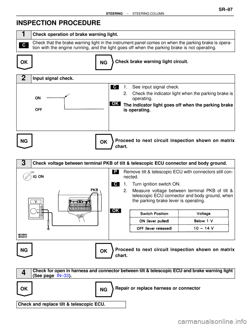
1Check operation of brake warning light.
Check that the brake warning light in the instrument panel comes on when the \
parking brake is opera-
tion with the engine running, and the light goes off when the parking brake is not operating.C
Check brake warning light circuit.
2Input signal check.
C
OK
1. See input signal check.
2. Check the indicator light when the parking brake isoperating.
The indicator light goes off when the parking brake
is operating.
Proceed to next circuit inspection shown on matrix
chart.
3Check voltage between terminal PKB of tilt & telescopic ECU connector and bod\
y ground.
C
OK
PRemove tilt & telescopic ECU with connectors still con-
nected.
1. Turn ignition switch ON.
2. Measure voltage between terminal PKB of tilt & telescopic ECU connector and body ground, when
the parking brake lever is operating.
Proceed to next circuit inspection shown on matrix
chart.
4Check for open in harness and connector between tilt & telescopic ECU and brak\
e warning light
(See page IN±33).
.
Repair or replace harness or connector
Check and replace tilt & telescopic ECU.
±
STEERING STEERING COLUMNSR±97
WhereEverybodyKnowsYourName
Page 3070 of 4087

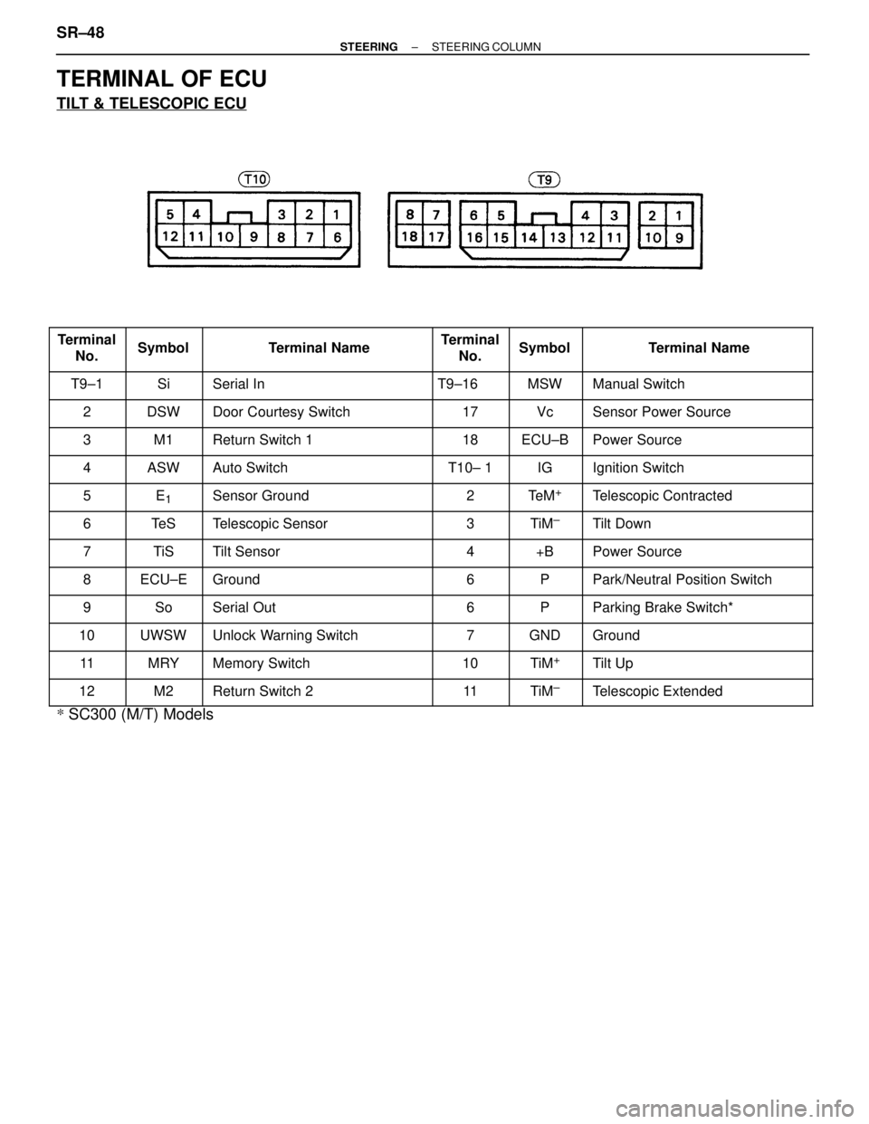
TERMINAL OF ECU
TILT & TELESCOPIC ECU
���� �
���
�
���
����
Terminal
No.
����� �
����
�
����
�����
Symbol
����������� �
����������
�
����������
�����������
Terminal Name
����� �
����
�
����
�����
Terminal
No.
���� �
���
�
���
����
Symbol
������������ �
�����������
�
�����������
������������
Terminal Name
���� ����T9±1����� �����Si����������� �����������Serial In����� �����T9±16���� ����MSW������������ ������������Manual Switch
���� ����2����� �����DSW����������� �����������Door Courtesy Switch����� �����17���� ����Vc������������ ������������Sensor Power Source
���� ����3����� �����M1����������� �����������Return Switch 1����� �����18���� ����ECU±B������������ ������������Power Source���� �
���
����4
����� �
����
�����ASW
����������� �
����������
�����������Auto Switch
����� �
����
�����T10± 1
���� �
���
����IG
������������ �
�����������
������������Ignition Switch
���� ����5����� �����E1����������� �����������Sensor Ground����� �����2���� ����Te M+������������ ������������Telescopic Contracted
���� ����6����� �����Te S����������� �����������Telescopic Sensor����� �����3���� ����TiM±������������ ������������Tilt Down
���� �
���7����� �
����TiS����������� �
����������Tilt Sensor����� �
����4���� �
���+B������������ �
�����������Power Source���� �
���
����8
����� �
����
�����ECU±E
����������� �
����������
�����������Ground
����� �
����
�����6
���� �
���
����P
������������ �
�����������
������������Park/Neutral Position Switch
���� ����9����� �����So����������� �����������Serial Out����� �����6���� ����P������������ ������������Parking Brake Switch*
���� ����10����� �����UWSW����������� �����������Unlock Warning Switch����� �����7���� ����GND������������ ������������Ground���� �
���
����11����� �
����
�����MRY����������� �
����������
�����������Memory Switch����� �
����
�����10���� �
���
����TiM+������������ �
�����������
������������Tilt Up
���� ����12����� �����M2����������� �����������Return Switch 2����� �����11���� ����TiM±������������ ������������Telescopic Extended
*
SC300 (M/T) Models
SR±48
±
STEERING STEERING COLUMN
WhereEverybodyKnowsYourName
Page 3241 of 4087
REAR SHOCK ABSORBER REMOVAL
SA0SC±02
1. JACK UP VEHICLE AND REMOVE REAR WHEEL
2. REMOVE REAR BRAKE CALIPER
(a) Remove the 2 bolts and remove the brake caliper from therear axle carrier.
(b) Hang up the brake caliper using wire, etc.
3. REMOVE SHOCK ABSORBER WITH COIL SPRING
(a) Remove the nut and bolt on lower side of the shock absorber.
(b) Remove the absorber cap.
(c) Loosen the nut in the middle of the suspension support.
NOTICE: Only loosen the nut, do not remove it.
(d) Remove the 3 nuts and shock absorber with the coil spring.
SA±108
±
SUSPENSION AND AXLE REAR SUSPENSION
WhereEverybodyKnowsYourName