Page 1890 of 4087
3. REMOVE VACUUM CONTROL VALVE SET(a) Disconnect the connector from the VSV.
(b) Disconnect the following hoses:(1) Vacuum hose from VSV
(2) Vacuum hose from vacuum pipe
(c) Remove the two nuts and vacuum control valve set.
4. REMOVE VACUUM TANK AND VSV Remove the screw, vacuum hose and VSV from the vacuum
tank.
5. REMOVE OIL DIPSTICK FOR ENGINE
6. DISCONNECT NO. 2 VACUUM PIPE Remove the two nuts and disconnect the vacuum pipe.
7. REMOVE EGR PIPE (a) Loosen the union nut.
(b) Remove the two bolts, EGR pipe and gasket.
8. REMOVE AIR INTAKE CHAMBER (a) Disconnect the following hoses:(1) Vacuum hose from brake booster union
(2) Air hose (from charcoal canister)
(3) Vacuum hose from vacuum pipe
(4) Vacuum sensing hose
(5) Air hose (from PS air control valve)
FI±58
±
EFI SYSTEM
Air Induction System (Acoustic Control Induction System (ACIS)
WhereEverybodyKnowsYourName
Page 1893 of 4087

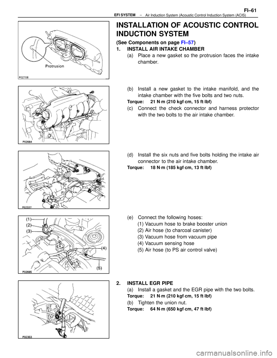
INSTALLATION OF ACOUSTIC CONTROL
INDUCTION SYSTEM
(See Components on page FI±57)
1. INSTALL AIR INTAKE CHAMBER (a) Place a new gasket so the protrusion faces the intake
chamber.
(b) Install a new gasket to the intake manifold, and the intake chamber with the five bolts and two nuts.
Torque: 21 N Vm (210 kgf Vcm, 15 ft Vlbf)
(c) Connect the check connector and harness protector
with the two bolts to the air intake chamber.
(d) Install the six nuts and five bolts holding the intake air connector to the air intake chamber.
Torque: 18 N Vm (185 kgf Vcm, 13 ft Vlbf)
(e) Connect the following hoses:
(1) Vacuum hose to brake booster union
(2) Air hose (to charcoal canister)
(3) Vacuum hose from vacuum pipe
(4) Vacuum sensing hose
(5) Air hose (to PS air control valve)
2. INSTALL EGR PIPE (a) Install a gasket and the EGR pipe with the two bolts.
Torque: 21 N Vm (210 kgf Vcm, 15 ft Vlbf)
(b) Tighten the union nut.
Torque: 64 N Vm (650 kgf Vcm, 47 ft Vlbf)
±
EFI SYSTEMFI±61Air Induction System (Acoustic Control Induction System (ACIS)
WhereEverybodyKnowsYourName
Page 2021 of 4087

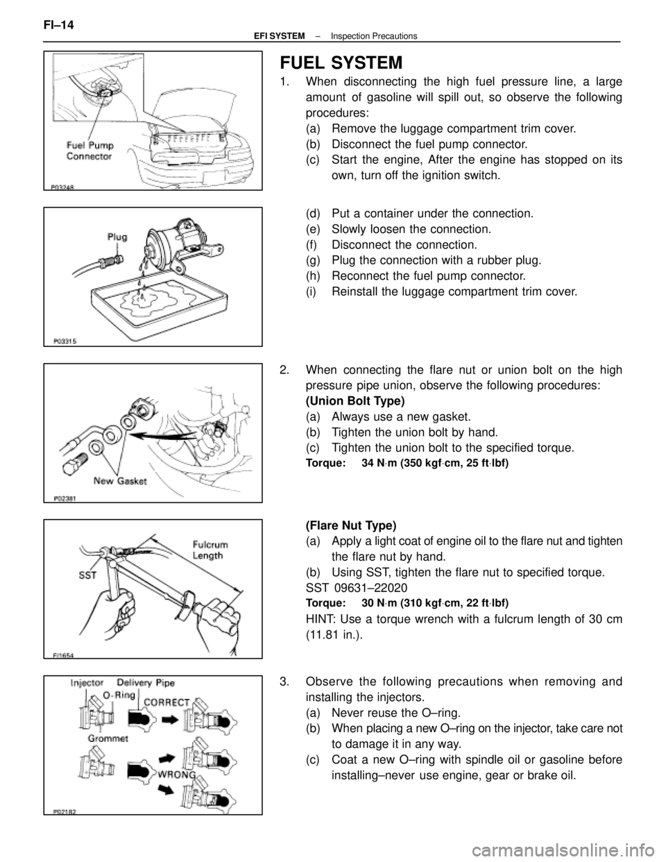
FUEL SYSTEM
1. When disconnecting the high fuel pressure line, a largeamount of gasoline will spill out, so observe the following
procedures:
(a) Remove the luggage compartment trim cover.
(b) Disconnect the fuel pump connector.
(c) Start the engine, After the engine has stopped on itsown, turn off the ignition switch.
(d) Put a container under the connection.
(e) Slowly loosen the connection.
(f) Disconnect the connection.
(g) Plug the connection with a rubber plug.
(h) Reconnect the fuel pump connector.
(i) Reinstall the luggage compartment trim cover.
2. When connecting the flare nut or union bolt on the high pressure pipe union, observe the following procedures:
(Union Bolt Type)
(a) Always use a new gasket.
(b) Tighten the union bolt by hand.
(c) Tighten the union bolt to the specified torque.
Torque: 34 N Vm (350 kgf Vcm, 25 ft Vlbf)
(Flare Nut Type)
(a) Apply a light coat of engine oil to the flare nut and tighten
the flare nut by hand.
(b) Using SST, tighten the flare nut to specified torque.
SST 09631±22020
Torque: 30 N Vm (310 kgf Vcm, 22 ft Vlbf)
HINT: Use a torque wrench with a fulcrum length of 30 cm
(11.81 in.).
3. Observe the following precautions when removing and installing the injectors.
(a) Never reuse the O±ring.
(b) When placing a new O±ring on the injector, take care not
to damage it in any way.
(c) Coat a new O±ring with spindle oil or gasoline before installing±never use engine, gear or brake oil.
FI±14
±
EFI SYSTEM Inspection Precautions
WhereEverybodyKnowsYourName
Page 2026 of 4087

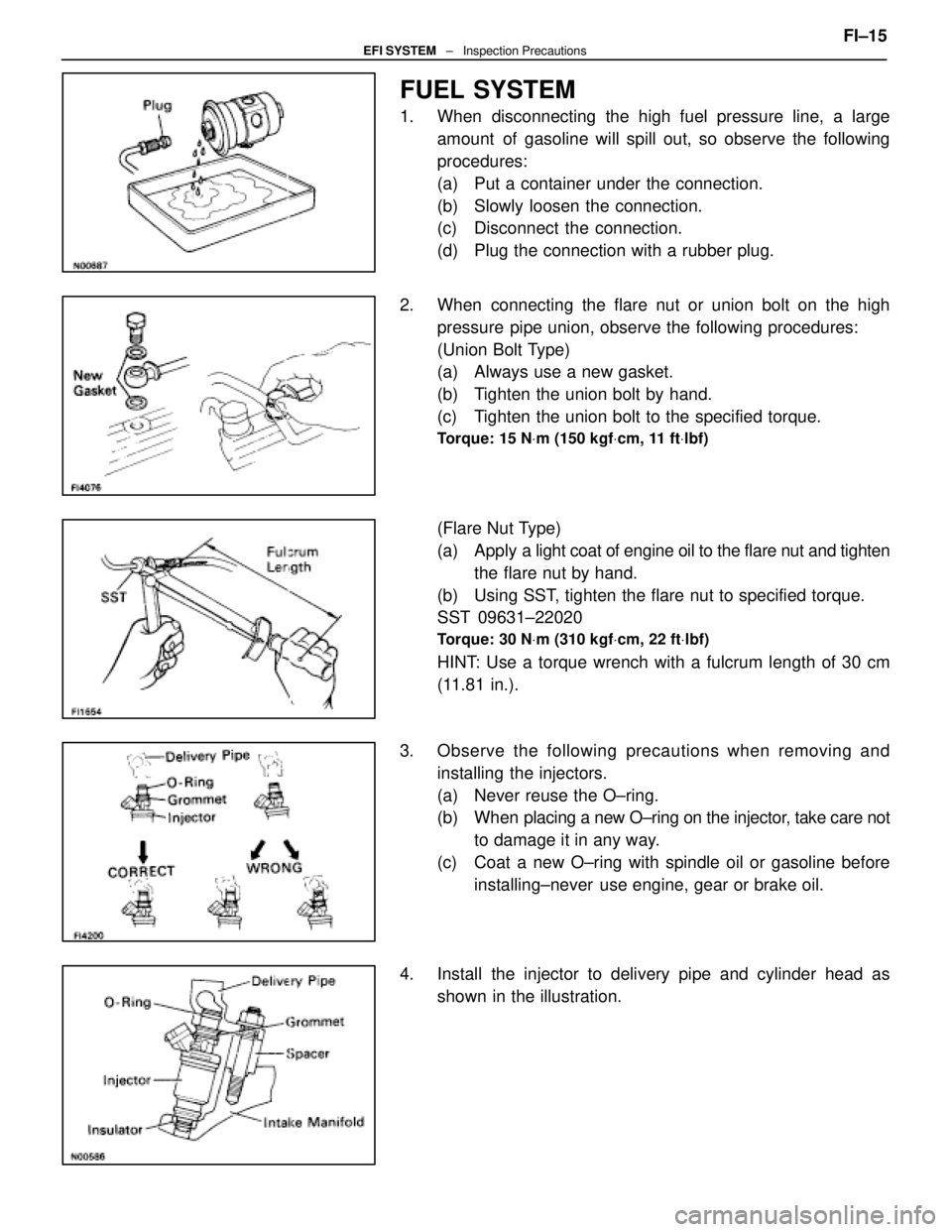
FUEL SYSTEM
1. When disconnecting the high fuel pressure line, a largeamount of gasoline will spill out, so observe the following
procedures:
(a) Put a container under the connection.
(b) Slowly loosen the connection.
(c) Disconnect the connection.
(d) Plug the connection with a rubber plug.
2. When connecting the flare nut or union bolt on the high pressure pipe union, observe the following procedures:
(Union Bolt Type)
(a) Always use a new gasket.
(b) Tighten the union bolt by hand.
(c) Tighten the union bolt to the specified torque.
Torque: 15 N Vm (150 kgf Vcm, 11 ft Vlbf)
(Flare Nut Type)
(a) Apply a light coat of engine oil to the flare nut and tighten
the flare nut by hand.
(b) Using SST, tighten the flare nut to specified torque.
SST 09631±22020
Torque: 30 N Vm (310 kgf Vcm, 22 ft Vlbf)
HINT: Use a torque wrench with a fulcrum length of 30 cm
(11.81 in.).
3. Observe the following precautions when removing and installing the injectors.
(a) Never reuse the O±ring.
(b) When placing a new O±ring on the injector, take care not
to damage it in any way.
(c) Coat a new O±ring with spindle oil or gasoline before installing±never use engine, gear or brake oil.
4. Install the injector to delivery pipe and cylinder head as shown in the illustration. FI±15
EFI SYSTEM
± Inspection Precautions
WhereEverybodyKnowsYourName
Page 2052 of 4087
15. DISCONNECT HOSESDisconnect the following hoses:(1) Water by±pass hose (from water inlet housing) from ISC valve
(2) Vacuum hose (from PS air control valve) from air in-
take chamber
(3) Vacuum sensing hose (from fuel pressure regula- tor) from vacuum pipe
(4) Two vacuum hoses (from VSV for EVAP system) from vacuum pipe
(5) Vacuum hose (from charcoal canister) from vacu- um pipe
(6) Water by±pass hose (from EGR valve) from water by±pass pipe
(7) Vacuum hose (from brake booster) from air intake
chamber
(8) Vacuum hose (from VSV for heater water valve) from air intake chamber
(9) PCV hose from LH cylinder head cover
16. REMOVE AIR INTAKE CHAMBER (a) Remove the bolt, stud bolt and accelerator bracket. FI±31
EFI SYSTEM
± Fuel System (Cold Start Injector)
WhereEverybodyKnowsYourName
Page 2058 of 4087
(g) Install the accelerator bracket with the bolt and stud bolt.
3. CONNECT HOSES Connect the following hoses:(1) Water by±pass hose (from EGR valve) to water by±
pass pipe
(2) Vacuum hose (from brake booster) to air intake chamber
(3) Vacuum hose (from VSV for heater water valve) to
air intake chamber
(4) PCV hose to LH cylinder head cover
(5) Water by±pass hose (from water inlet housing) to ISC valve
(6) Vacuum hose (from PS air control valve) to air in- take chamber
(7) Vacuum sensing hose (from fuel pressure regula- tor) to vacuum pipe
(8) Two vacuum hoses (from VSV for EVAP system) to
vacuum pipe
(9) Vacuum hose (from charcoal canister) to vacuum pipe FI±37
EFI SYSTEM
± Fuel System (Cold Start Injector)
WhereEverybodyKnowsYourName
Page 2151 of 4087

SERVICE SPECIFICATIONS
SERVICE DATA
MA002±0B����� �
����
�
����
�
����
�
����
�����
Engine���������� �
���������
�
���������
�
���������
�
���������
����������
Spark plug
Recommended spark plug
Correct electrode gap
Firing order
Valve clearance������ �
�����
�
�����
�
�����
�
�����
������
ND
NGK
Intake
Exhaust
������������������\
�
�����������������
�
�����������������
�
�����������������
�
�����������������
������������������\
PK20R11
BKR6EP11
1.1 mm (0.043 in.)
1 ± 8 ± 4 ± 3 ± 6 ± 5 ± 7 ± 2
0.15 ± 0.25 mm (0.006 ± 0.010 in.)
0.25 ± 0.35 mm (0.010 ± 0.014 in.)
����� �
����
�
����
�
����
�����
BrakeFront and rear brakes
Pad thickness
Disc thickness
Limit
Limit (Front) (Rear)1.0 mm (0.039 in.)
30.0 mm (1.181 in.)
15.0 mm (0.591 in.)
����� �
����
�
����
�����
Disc runout
Parking brake
Lining thickness
Drum inside diameter
()
Limit
Limit
Limit
()
0.05 mm (0.0020 in.)
1.0 mm (0.039 in.)
191 mm (7.520 in.)
����� �����ChassisSteering linkage
Steering wheel freeplay
Limit30 mm (1.18 in.)����� �
����
�����
gy
Ball joint
Vertical play
Limit
()
0.3 mm (0.012 in.)
MA002±0B
TORQUE SPECIFICATIONS
������������������\
�� ������������������\
��Part tightened������� �������N
Vm������ ������kgf Vcm������ ������ft Vlbf
���������������� ����������������Spark plug x Cylinder head1818013
���������������� ����������������Front seat x Body3737527
���������������� ����������������Front suspension crossmember x Body����� �����for nut1271,30094
���������������� ��������������������� �����for bolt 201
,
2,050148
���������������� ����������������Rear suspension member x Body1761,800130
���������������� ����������������Rear suspension member rear cushion x Body3839028
±
MAINTENANCE (1UZ ± FE)MA±21
WhereEverybodyKnowsYourName
Page 2154 of 4087
V04535
(4) Also applicable to drum lining for parking brake. For other usage condit\
ions, refer to SCHEDULE B.
(5) Check for leakage.
(6) Check for oil leaks from steering gear housing.
(7) Applicable only when operating mainly on rough, muddy roads. The applicable parts \
are listed below. Forother usage conditions, refer to SCHEDULE B.
�Front and rear suspension member to cross body.
� Bolts for seat installation.
±
MAINTENANCE (1UZ ± FE)MA±3
WhereEverybodyKnowsYourName