Page 2956 of 4087
WIRING DIAGRAM
CIRCUIT INSPECTION
Parking Brake Switch Circuit
CIRCUIT DESCRIPTION
When the parking brake is operating, the parking brake switch sends a signal\
to the ECU. When this signal
is input to the ECU during tilt & telescopic, the ECU cancels tilt & tel\
escopic.
DIAGNOSTIC CHARTDIAGNOSTIC CHART
SR±96±
STEERING STEERING COLUMN
WhereEverybodyKnowsYourName
Page 2958 of 4087
SR±52).
WIRING DIAGRAM
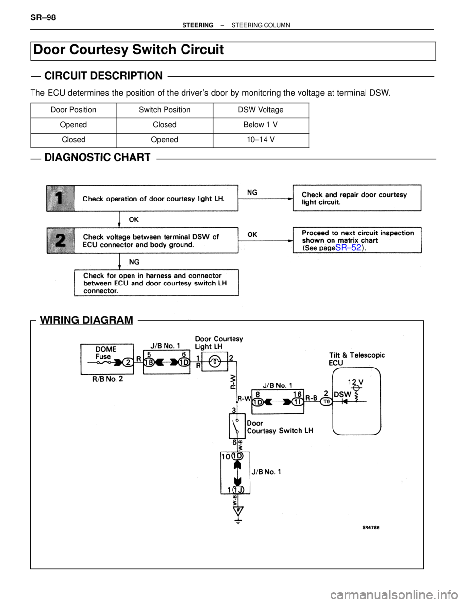
Door Courtesy Switch Circuit
CIRCUIT DESCRIPTION
The ECU determines the position of the driver's door by monitoring the voltage at terminal DSW.
�������� �
�������
��������Door Position���������� �
���������
����������Switch Position��������� �
��������
���������DSW Voltage
�������� ��������Opened���������� ����������Closed��������� ���������Below 1 V
�������� ��������Closed���������� ����������Opened��������� ���������10±14 V
DIAGNOSTIC CHARTDIAGNOSTIC CHART
SR±98±
STEERING STEERING COLUMN
WhereEverybodyKnowsYourName
Page 3016 of 4087
ELECTRONIC CONTROL COMPONENTS
INSPECTION
SOLENOID VALVE
SR0GU±01
1. DISCONNECT WIRING CONNECTOR
2. MEASURE RESISTANCEMeasure the resistance between SOL � and SOL �.
Resistance:
6.0±11.0 �
3. CHECK SOLENOID OPERATION
(a) Connect the battery positive terminal to the solenoid terminal
SOL �.
(b) C onnect the battery negative terminal to the solenoid
terminal SOL �.
(c) Check that the solenoid is clicked. If faulty, replace the pressure control valve with the solenoid
valve.
NOTICE:
w Do not apply voltage for more than 30 seconds to avoid
burning out the solenoid.
w If repeating this step, wait until the solenoid cools down
enough that it can be touched by hand.
4. CONNECT WIRING CONNECTOR
±
STEERING POWER STEERINGSR±167
WhereEverybodyKnowsYourName
Page 3033 of 4087
 Check that the front wheels are facing straight ahead.
(b) Turn the spiral cable counterclockwise by hand until it
becomes harder to turn the cable.
(c) Then rotate the")
4. CENTER SPIRAL CABLE
(a) Check that the front wheels are facing straight ahead.
(b) Turn the spiral cable counterclockwise by hand until it
becomes harder to turn the cable.
(c) Then rotate the spiral cable clockwise about 3 turns to align the red mark.
HINT: The spiral cable will rotate about 3 turns to either left
or right of the center.
5. INSTALL STEERING WHEEL
(a) Align matchmarks on the steering wheel and main shaft, and install the wheel to the shaft.
(b) Tighten the wheel set nut.
Torque: 35 N Vm (360 kgf Vcm, 26 ft Vlbf)
(c) Connect the connector.
6. INSTALL STEERING WHEEL PAD
(a) Connect the Airbag connector.
(b) Install the pad after confirming that the circumference groove
of the torx screws is caught on the screw case.
(c) Using a torx wrench, tighten the 4 torx screws.
Torque: 7.4 N Vm (75 kgf Vcm, 65 in. Vlbf)
NOTICE:
w Make sure the wheel pad is installed to the specified
torque.
w If the wheel pad has been dropped, or there are cracks,
dents or other defects in the case or connector, replace
the wheel pad with a new one.
w When installing the wheel pad, take care that the wiring
does not interfere with other parts and is not pinched
between other parts.
7. CHECK STEERING WHEEL CENTER POINT
8. CONNECT NEGATIVE (±) TERMINAL CABLE TO
BATTERY
±
STEERING STEERING COLUMNSR±11
WhereEverybodyKnowsYourName
Page 3068 of 4087
WIRING DIAGRAM
TILT & TELESCOPIC ECU
SR±46±
STEERING STEERING COLUMN
WhereEverybodyKnowsYourName
Page 3071 of 4087

STANDARD VALUE OF ECU TERMINAL
������ �
�����
������Terminals
������ �
�����
������Symbols
������ �
�����
������Wiring
Color��������������� �
��������������
���������������Condition
������� �
������
�������Standard
Value
������ �
�����
������T9±1������ �
�����
������Si������ �
�����
������B��������������� �
��������������
���������������
Tilt & telescopic ECU & power seat ECU
communication������� �
������
�������0 V
e12 V
������ ������T9±2 e������ ������DSW e������ ������R±Be��������������� ���������������Driver's door open������� �������Below 1 V
������ ������
T9 2 e
Body Ground������ ������
DSW e
Body Ground������ ������
RBe
Body GroundDriver's door closed1014 V
������ ������T9±3 eT9±8������ ������M1 eECU±E������ ������Pe BR±B��������������� ���������������Driving position memory & return switch ON������� �������Below 1 V
������ ������T9±3eT9±8������ ������M1eECU±E������ ������PeBR±B��������������� ���������������Driving position memory & return switch OFF������� �������10
~ 14 V
������ ������T9±4
eT9±5������ ������ASW eE1������ ������V±W eBR��������������� ���������������Unlock warning switch ON, auto switch ON������� �������10 ~ 14 V
������ ������T9±4eT9±5������ ������ASWeE1������ ������V±WeBR��������������� ���������������Unlock warning switch ON, auto switch OFF������� �������Below 1 V
������ ������T9±5������ ������E1������ ������BR��������������� ���������������Always������� �������Below 1 V
������ �
�����
������T9±6
eT9±5
������ �
�����
������Te S
eE1
������ �
�����
������Y±R
eBR
��������������� �
��������������
���������������
Unlock warning switch ON, telescopic fully
forward������� �
������
�������Below 2 V
������ ������
T9±6eT9±5
������ ������
TeSeE1
������ ������
Y±ReBR
��������������� ���������������Unlock warning switch ON, telescopic fully
backward������� �������4±6 V
������ ������
T9±7
eT9±5
������ ������
TiS eE1
������ ������
P±L eBR
��������������� ���������������Unlock warning switch ON, tilt fully raised������� �������Below 2 V������ ������T9±7eT9±5������ ������TiSeE1������ ������P±LeBR��������������� ���������������Unlock warning switch ON, tilt fully lowered������� �������4±6 V������ ������T9±8������ ������ECU±E������ ������BR±B��������������� ���������������Always������� �������Below 1 V������ �
�����
������T9±9
������ �
�����
������So
������ �
�����
������W
��������������� �
��������������
���������������Tilt & telescopic ECU & power seat ECU
communication������� �
������
�������0 V
e12 V
������ ������T9±10 e������ ������UWSW e������ ������Ye��������������� ���������������Ignition key inserted in the key cylinder������� �������Below 1 V
������ ������T9 10 e
Body Ground������ ������UWSW e
Body Ground������ ������Ye
Body Ground��������������� ���������������Ignition key pulled out from the key cylinder������� �������10
~ 14 V
������ ������
T9±11 eT9±8
������ ������
MRY eECU±E
������ ������
R±Y eBR±B
��������������� ���������������Auto set switch ON������� �������Below 1 V
������ ������T9±11eT9±8������ ������MRYeECU±E������ ������R±YeBR±B��������������� ���������������Auto set switch OFF������� �������10 ~ 14 V
������ ������
T9±12 eT9±8
������ ������
M2 eECU±E
������ ������
P±B eBR±B
��������������� ���������������Driving position memory & return switch ON������� �������Below 1 V
������ ������T9±12eT9±8������ ������M2eECU±E������ ������P±BeBR±B��������������� ���������������Driving position memory & return switch OFF������� �������10 ~ 14 V
������ �
�����
������
������ �
�����
������
������ �
�����
������
��������������� �
��������������
���������������
Unlock warning switch ON
Telescopic extend by manual switch������� �
������
�������2.6 V
������ �
�����
������
������ �
�����
������
������ �
�����
������
��������������� �
��������������
���������������
Unlock warning switch ON
Tilt up by manual switch������� �
������
�������3.5 V
������ ������T9±16
eT9±17������ ������MSW eVC������ ������V±Y eR±W��������������� ���������������Unlock warning switch ON
Telescopic contracted by manual switch������� �������4.2 V
������ �
�����
������
������ �
�����
������
������ �
�����
������
��������������� �
��������������
���������������Unlock warning switch ON
Tilt down by manual switch������� �
������
�������4.6 V
������ �
�����
������
������ �
�����
������
������ �
�����
������
��������������� �
��������������
���������������
Unlock warning switch ON, manual switch
OFF������� �
������
�������4±6 V
±
STEERING STEERING COLUMNSR±49
WhereEverybodyKnowsYourName
Page 3072 of 4087

STANDARD VALUE OF ECU TERMINAL
������ �
�����
������Terminals
������ �
�����
������Symbols
����� �
����
�����
Wiring
Color��������������� �
��������������
���������������Condition
�������� �
�������
��������
Standard
Value
������ ������T9±17 eT9±5������ ������Vc eE1����� �����R±W eBR��������������� ���������������Unlock warning switch ON�������� ��������4±6 V
������ ������T9±17eT9±5������ ������VceE1����� �����R±WeBR��������������� ���������������Unlock warning switch OFF�������� ��������Below 1 V
������ ������T9±18������ ������ECU±B����� �����R��������������� ���������������Always�������� ��������10 ~ 14 V
������ ������T10±1 e������ ������IGe����� �����B±R e��������������� ���������������Ignition switch ON�������� ��������10 ~ 14 V
������ ������
T10 1 e
Body Ground������ ������
IGe
Body Ground����� �����
BR e
Body Ground��������������� ���������������Ignition switch OFF�������� ��������Below 1 V
������ �
�����
������T10±2
e
Body Ground
������ �
�����
������Te M+e
Body Ground
����� �
����
�����L±B
e
Body Ground
��������������� �
��������������
���������������
Unlock warning switch ON, telescopic
forward�������� �
�������
��������10 ~ 14 V
������ ������Body Ground������ ������Body Ground����� �����Body Ground��������������� ���������������Except above mention�������� ��������Below 1 V
������ ������T10±3
e������ ������TiM±e����� �����R±Le��������������� ���������������Unlock warning switch ON, tilt down�������� ��������10 ~ 14 V
������ ������
T10 3 e
Body Ground������ ������
TiMe
Body Ground����� �����
RLe
Body Ground��������������� ���������������Except above mention�������� ��������Below 1 V
������ ������T10±4������ ������+B����� �����L±W��������������� ���������������Always�������� ��������10 ~ 14 V
������ ������T10±6 e������ ������Pe����� �����GR e��������������� ���������������Ignition switch ON, shift lever ªPº position�������� ��������10 ~ 14 V
������ ������
T10 6 e
Body Ground������ ������
Pe
Body Ground����� �����
GR e
Body Ground��������������� ���������������Ignition switch ON, except above mention�������� ��������Below 1 V
������ ������T10±6 e������ ������Pe����� �����GR e��������������� ���������������Ignition switch ON, PKB lever pulled�������� ��������Below 1 V
������ ������
T10 6 e
Body Ground������ ������
Pe
Body Ground����� �����
GR e
Body Ground��������������� ���������������Ignition switch ON, PKB lever released�������� ��������10 ~ 14 V
������ ������T10±7������ ������GND����� �����W±B��������������� ���������������Always�������� ��������Below 1 V
������ ������T10±10 e������ ������TiM+e����� �����R±Be��������������� ���������������Unlock warning switch ON, tilt up�������� ��������10 ~ 14 V
������ ������
T10 10 e
Body Ground������ ������
TiMe
Body Ground����� �����
RBe
Body Ground��������������� ���������������Except above mention�������� ��������Below 1 V
������ ������T10±11 e
Body Ground
������ ������Te M±e
Body Ground
����� �����L±Ye
Body Ground
��������������� ���������������Unlock warning switch ON, telescopic
backward�������� ��������10 ~ 14 V
������ ������Body Ground������ ������Body Ground����� �����Body Ground��������������� ���������������Except above mention�������� ��������Below 1 V
TILT & TELESCOPIC ECU
SR±50±
STEERING STEERING COLUMN
WhereEverybodyKnowsYourName
Page 3084 of 4087
SR±52).
IN±33).
WIRING DIAGRAM
CIRCUIT INSPECTION
ECU Power Source Circuit
CIRCUIT DESCRIPTION
The ECU power source also supplies power to the CPU and sensor, etc. Power is supplied to the ECU even
when the ignition switch is off.
DIAGNOSTIC CHARTDIAGNOSTIC CHART
SR±62±
STEERING STEERING COLUMN
WhereEverybodyKnowsYourName


.
IN±33).
WIRING DIAGRAM
CIRCUIT INSPECTION
ECU Power Source Circuit
CIRCUIT DESCRIPTION
The ECU power source also supplies power to the CPU and sensor, etc. Power is supplied to the ECU even")