Page 2695 of 4087
DIAGNOSTIC CHART
DIAGNOSTIC
CHART
HINT:
wWhen other codes are output in addition to 27 and 29 at the same time, check the ci\
rcuits for other
codes first.
w If diag. code 27 is displayed, check left bank sub±oxygen sensor circ\
uit, and if 29 is displayed,
check right bank sub±oxygen sensor circuit.
WIRING DIAGRAM
Check voltage of terminals HTL2, HTR2.
Check resistance of sub±oxygen sensor heater.
Check and repair sub±oxygen sensor heater
circuit.
Check operation of sub±oxygen sensor heater.
Check and replace ECU. Replace main oxygen sensor.
*: In this case, oxygen sensor can be deteriorated.
Replace main oxygen sensor.*
TR±84±
ENGINE TROUBLESHOOTING Circuit Inspection
WhereEverybodyKnowsYourName
Page 2700 of 4087
DIAGNOSTIC CHART
DIAGNOSTIC
CHART
WIRING DIAGRAM
Check and replace ECU.Replace air flow meter. Check and replace ECU.
Check voltage of air flow meter power source. Check voltage terminal KS of ECU.
Check for open and short in harness and
connector between air flow meter and ECU. Check voltage of terminal KS.
Repair or repolace harness or
connector
When diag. code 31 is displayed,
check and replace ECU.
±
ENGINE TROUBLESHOOTING Circuit InspectionTR±89
WhereEverybodyKnowsYourName
Page 2706 of 4087
DIAGNOSTIC CHART
DIAGNOSTIC
CHART
HINT:
wIf diag. code 41 is displayed, check throttle position sensor circuit; if d\
iag. code 47 is displayed,
check sub±throttle position sensor circuit.
w If diag. codes º22º (water temperature sensor circuit), º24º\
(intake air temperature sensor circuit)
and º41º (throttle position sensor circuit) are output simultaneous\
ly, E2 (sensor ground) may be
open.
WIRING DIAGRAM
Check and replace ECU. Adjust or replace throttle position
sensor.
Check for momentary interruption
(See page
TR±23).
Repair or replace harness or
connector.
Check voltage of throttle position sensor.
Check operation for throttle position sensor.
Check for open and short in harness and
connector between throttle position sensor and ECU.
±
ENGINE TROUBLESHOOTING Circuit InspectionTR±95
WhereEverybodyKnowsYourName
Page 2709 of 4087

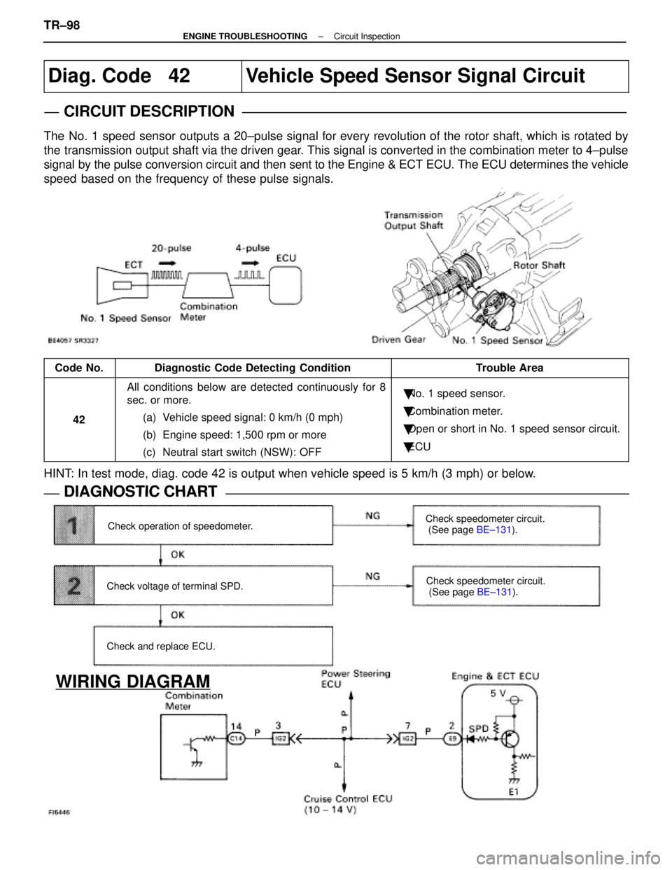
Diag. Code 42Vehicle Speed Sensor Signal Circuit
CIRCUIT DESCRIPTION
The No. 1 speed sensor outputs a 20±pulse signal for every revolution of the rotor shaft, which is r\
otated by
the transmission output shaft via the driven gear. This signal is converted in the combination meter to 4±pulse
signal by the pulse conversion circuit and then sent to the Engine & ECT ECU. \
The ECU determines the vehicle
speed based on the frequency of these pulse signals.
Code No.Diagnostic Code Detecting ConditionTrouble Area
42
All conditions below are detected continuously for 8
sec. or more.(a) Vehicle speed signal: 0 km/h (0 mph)
(b) Engine speed: 1,500 rpm or more
(c) Neutral start switch (NSW): OFF�No. 1 speed sensor.
� Combination meter.
� Open or short in No. 1 speed sensor circuit.
� ECU
HINT: In test mode, diag. code 42 is output when vehicle speed is 5 km/h (3\
mph) or below.
DIAGNOSTIC CHARTDIAGNOSTIC CHART
Check operation of speedometer.
Check voltage of terminal SPD.
Check and replace ECU. Check speedometer circuit.
(See page
BE±131).
Check speedometer circuit.
(See page BE±131).
WIRING DIAGRAM
TR±98±
ENGINE TROUBLESHOOTING Circuit Inspection
WhereEverybodyKnowsYourName
Page 2711 of 4087

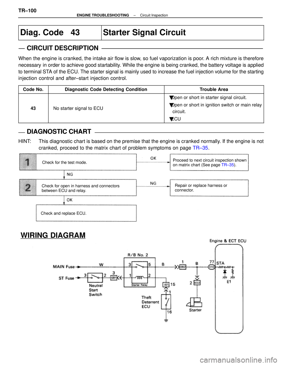
Diag. Code 43Starter Signal Circuit
CIRCUIT DESCRIPTION
When the engine is cranked, the intake air flow is slow, so fuel vaporization is poor. A rich mixture is therefore
necessary in order to achieve good startability. While the engine is being cranked, the battery voltage is applied
to terminal STA of the ECU. The starter signal is mainly used to increase the fuel inj\
ection volume for the starting
injection control and after±start injection control.
Code No.Diagnostic Code Detecting ConditionTrouble Area
43No starter signal to ECU
�Open or short in starter signal circuit.
� Open or short in ignition switch or main relay
circuit.
� ECU
DIAGNOSTIC CHARTDIAGNOSTIC CHART
HINT: This diagnostic chart is based on the premise that the engine is cranked nor\
mally. If the engine is not
cranked, proceed to the matrix chart of problem symptoms on page TR±35.
Check for the test mode.
Check for open in harness and connectors
between ECU and relay.
Check and replace ECU. Proceed to next circuit inspection shown
on matrix chart (See page
TR±35).
Repair or replace harness or
connector.
WIRING DIAGRAM
TR±100±
ENGINE TROUBLESHOOTING Circuit Inspection
WhereEverybodyKnowsYourName
Page 2715 of 4087
DIAGNOSTIC CHART
HINT: If diag. code 52 is displayed, check No. 1 knock sensor (for left bank)\
circuit.If diag. code 55 is displayed, check No. 2 knock sensor (for right bank\
) circuit.
If diag. code 53 is displayed, replace engine & ECT ECU.
Does malfunction disappear when a good knock
sensor is installed? Repair or replace harness or
connector.
Replace knock sensor.
Check no continuity of knock sensor circuit.
Check knock sensor.
Check for open and short in harness and
connector between knock sensor and ECU.
Replace knock sensor.
Check and replace ECU.
WIRING DIAGRAM
TR±104±
ENGINE TROUBLESHOOTING Circuit Inspection
WhereEverybodyKnowsYourName
Page 2721 of 4087
DIAGNOSTIC CHART
WIRING DIAGRAM
Check voltage of terminal EGR 1 ~ 4.
Check voltage of EGR Step motor power
source.
Check resistance of EGR step motor.
Check for open and short in harness and
connector between EGR step motor and
ECU.
Check and replace ECU.
Check operation for EGR step motor.
Check resistance of EGR gas temp. sensor.
Check for open and short in harness and
connector between EGR gas temp. sensor
and ECU.
Check and replace ECU.
Replace EGR gas temp. sensor.
Replace EGR step motor.
Replace EGR step motor.
Repair or replace harness or
connector.
Repair or replace harness or
connector.
Check for ECU power source
circuit.
TR±110±
ENGINE TROUBLESHOOTING
WhereEverybodyKnowsYourName
Page 2725 of 4087

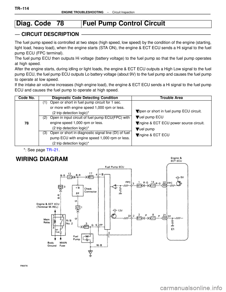
Diag. Code 78Fuel Pump Control Circuit
CIRCUIT DESCRIPTION
The fuel pump speed is controlled at two steps (high speed, low speed) by\
the condition of the engine (starting,
light load, heavy load), when the engine starts (STA ON), the engine & ECT ECU sends a Hi signal to the fuel
pump ECU (FPC terminal).
The fuel pump ECU then outputs Hi voltage (battery voltage) to the fuel p\
ump so that the fuel pump operates
at high speed.
After the engine starts, during idling or light loads, the engine & ECT ECU o\
utputs a High Low signal to the fuel
pump ECU, the fuel pump ECU outputs Lo battery voltage (about 9V) to the f\
uel pump and causes the fuel pump
to operate at low speed.
If the intake air volume increases (high engine load), the engine & ECT \
ECU sends a Hi signal to the fuel pump
ECU and causes the fuel pump to operate at high speed.
Code No.Diagnostic Code Detecting ConditionTrouble Area
(1) Open or short in fuel pump circuit for 1 sec. or more with engine speed 1,000 rpm or less.
(2 trip detection logic)*
�Open or short in fuel pump ECU circuit.
78
(2) Open in input circuit of fuel pump ECU(FPC) with
engine speed 1,000 rpm or less.
(2 trip detection logic)*�Fuel pump ECU
� Engine & ECT ECU power source circuit.
� Fuel pump
(3) Open or short in diagnostic signal line (DI) of fuel
pump ECU with engine speed 1,000 rpm or less.
(2 trip detection logic)*
�Fuel um
�Engine & ECT ECU
*: See page TR±21.
WIRING DIAGRAM
TR±114±
ENGINE TROUBLESHOOTING Circuit Inspection
WhereEverybodyKnowsYourName