Page 1998 of 4087
SERVICE DATA (Cont'd)
ECU (cont'd)Resistance of wiring connector side (cont'd)
TerminalsConditionSTD voltage (�)
±
HTR1
HTR2
HTL1
HTL2 +B
+B1±5.1 ± 6.3
±
PA G +B
+B1±30 ± 34
±IDL1 +BThrottle valve fully openInfinity
±IDL1
IDL2
+B
+B1Throttle valve fully closed2,300 or less
±VTA1E2
Throttle valve fully open3,300 ± 10,000
±VTA1
VTA2E2
Throttle valve fully closed200 ± 800
VC ± E2±4,000 ± 9,000
THS ± E2Intake air temp, 20
°C (68 °F)2,000 ± 3,000
THW ± E2Coolant temp. 80 °C (176 °F)200 ± 400
THG ± E2EGR gas temp. 50 °C (112 °F)69,400 ± 88,500
G1
G2 G1 (±)
G2 (±)
±Cam position sensor ± 10 ± +40
°C (14 ± 104 °F)835 ± 1,350
NE ± NE (±)engine speed sensor ± 10 ± +40 °C (14 ± 104 °F)835 ± 1,350
Fuel cut rpmw/ Vehicle speed 0 km/h and coolant temp. 80 °C (176 °F)
Fuel cut rpm
Fuel return rpm
1,800 rpm
1,400 rpm
FI±141EFI SYSTEM ± Service Specifications
WhereEverybodyKnowsYourName
Page 2019 of 4087

IF VEHICLE IS EQUIPPED WITH MOBILE
RADIO SYSTEM (HAM, CB, ETC.)
The ECU has been designed so that it will not be affected by out-
side interference. However, if your vehicle is equipped with a CB
radio transceiver, etc. (even one with about 10 W output), it may,
at times, have an effect upon ECU operation, especially if the an-
tenna and feeder are installed nearby.
Therefore, observe the following precautions:
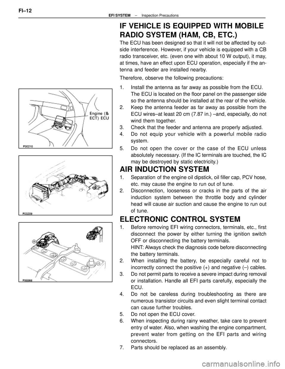
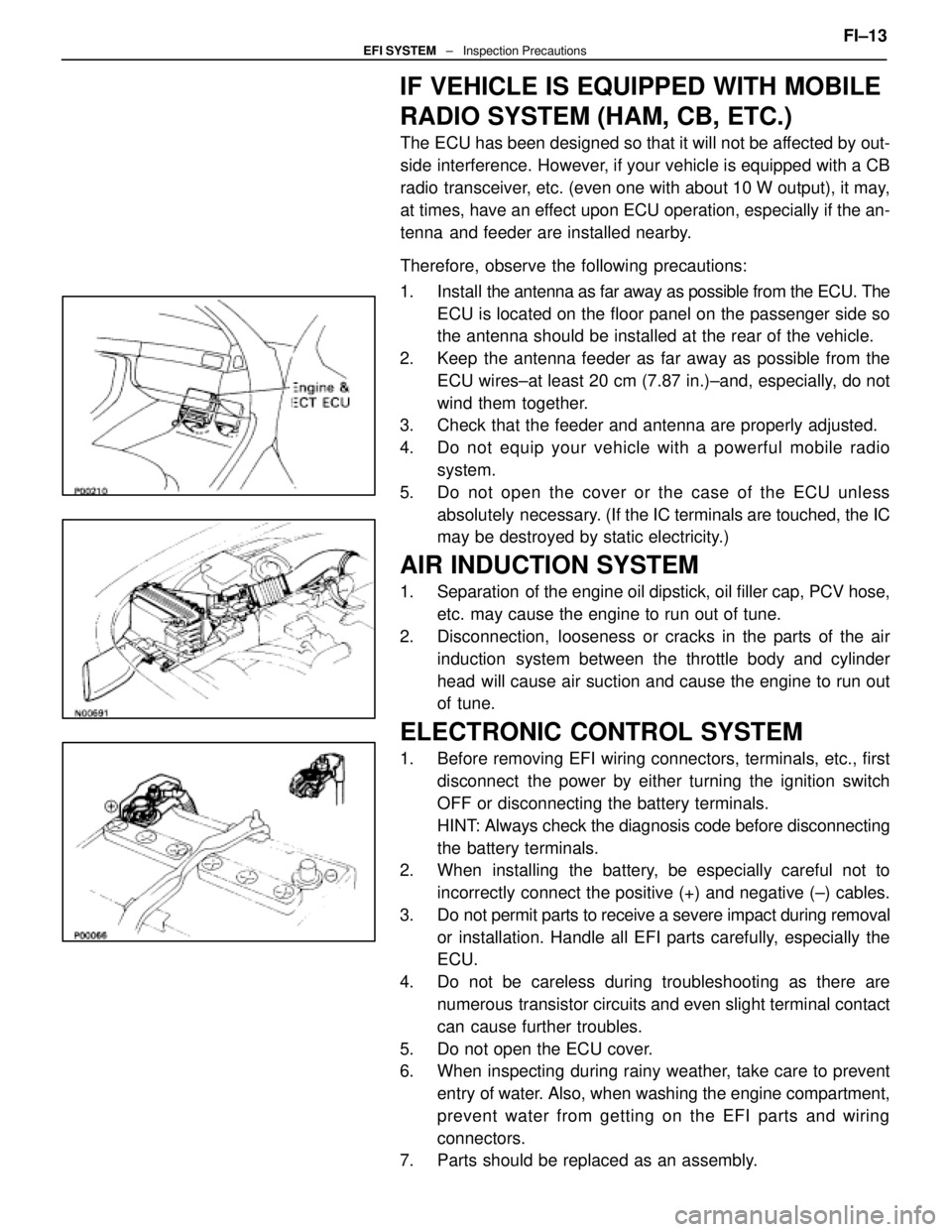
1. Install the antenna as far away as possible from the ECU. The ECU is located on the floor panel on the passenger side
so the antenna should be installed at the rear of the vehicle.
2. Keep the antenna feeder as far away as possible from the ECU wires±at least 20 cm (7.87 in.) ±and, especially, do not
wind them together.
3. Check that the feeder and antenna are properly adjusted.
4. Do not equip your vehicle with a powerful mobile radio
system.
5. Do not open the cover or the case of the ECU unless absolutely necessary. (If the IC terminals are touched, the IC
may be destroyed by static electricity.)
AIR INDUCTION SYSTEM
1. Separation of the engine oil dipstick, oil filler cap, PCV hose,
etc. may cause the engine to run out of tune.
2. Disconnection, looseness or cracks in the parts of the air
induction system between the throttle body and cylinder
head will cause air suction and cause the engine to run out
of tune.
ELECTRONIC CONTROL SYSTEM
1. Before removing EFI wiring connectors, terminals, etc., firstdisconnect the power by either turning the ignition switch
OFF or disconnecting the battery terminals.
HINT: Always check the diagnosis code before disconnecting
the battery terminals.
2. When installing the battery, be especially careful not to
incorrectly connect the positive (+) and negative (±) cables.
3. Do not permit parts to receive a severe impact during removal or installation. Handle all EFI parts carefully, especially the
ECU.
4. Do not be careless during troubleshooting as there are numerous transistor circuits and even slight terminal contact
can cause further troubles.
5. Do not open the ECU cover.
6. When inspecting during rainy weather, take care to prevent entry of water. Also, when washing the engine compartment,
prevent water from getting on the EFI parts and wiring
connectors.
7. Parts should be replaced as an assembly.
FI±12
±
EFI SYSTEM Inspection Precautions
WhereEverybodyKnowsYourName
Page 2020 of 4087
8. Care is required when pulling out and inserting wiring
connectors.
(a) Release the lock and pull out the connector, pulling on the connectors.
(b) Fully insert the connector and check that it is locked.
9. Use SST for inspection or test of the injector or its wiring connector.
SST 09842±30070
±
EFI SYSTEM Inspection PrecautionsFI±13
WhereEverybodyKnowsYourName
Page 2024 of 4087

IF VEHICLE IS EQUIPPED WITH MOBILE
RADIO SYSTEM (HAM, CB, ETC.)
The ECU has been designed so that it will not be affected by out-
side interference. However, if your vehicle is equipped with a CB
radio transceiver, etc. (even one with about 10 W output), it may,
at times, have an effect upon ECU operation, especially if the an-
tenna and feeder are installed nearby.
Therefore, observe the following precautions:
1. Install the antenna as far away as possible from the ECU. The
ECU is located on the floor panel on the passenger side so
the antenna should be installed at the rear of the vehicle.
2. Keep the antenna feeder as far away as possible from the ECU wires±at least 20 cm (7.87 in.)±and, especially, do not
wind them together.
3. Check that the feeder and antenna are properly adjusted.
4. Do not equip your vehicle with a powerful mobile radio
system.
5. Do not open the cover or the case of the ECU unless absolutely necessary. (If the IC terminals are touched, the IC
may be destroyed by static electricity.)
AIR INDUCTION SYSTEM
1. Separation of the engine oil dipstick, oil filler cap, PCV hose,
etc. may cause the engine to run out of tune.
2. Disconnection, looseness or cracks in the parts of the air induction system between the throttle body and cylinder
head will cause air suction and cause the engine to run out
of tune.
ELECTRONIC CONTROL SYSTEM
1. Before removing EFI wiring connectors, terminals, etc., firstdisconnect the power by either turning the ignition switch
OFF or disconnecting the battery terminals.
HINT: Always check the diagnosis code before disconnecting
the battery terminals.
2. When installing the battery, be especially careful not to
incorrectly connect the positive (+) and negative (±) cables.
3. Do not permit parts to receive a severe impact during removal or installation. Handle all EFI parts carefully, especially the
ECU.
4. Do not be careless during troubleshooting as there are numerous transistor circuits and even slight terminal contact
can cause further troubles.
5. Do not open the ECU cover.
6. When inspecting during rainy weather, take care to prevent entry of water. Also, when washing the engine compartment,
prevent water from getting on the EFI parts and wiring
connectors.
7. Parts should be replaced as an assembly. FI±13
EFI SYSTEM
± Inspection Precautions
WhereEverybodyKnowsYourName
Page 2025 of 4087
8. Care is required when pulling out and inserting wiring
connectors.
(a) Release the lock and pull out the connector, pulling on the connectors.
(b) Fully insert the connector and check that it is locked.
9. When inspecting a connector with a volt/ohmmeter. (a) Carefully take out the water±proofing rubber if it is a
water±proof type connector.
(b) Insert the test probe into the connector from wiring side when checking the continuity, amperage or voltage.
(c) Do not apply unnecessary force to the terminal.
(d) After checking, install the water±proofing rubber on the connector securely.
10. Use SST for inspection or test of the injector, cold start injector or its wiring connector.
SST 09842±30055 (A) and 09842±30070 (C)
FI±14
EFI SYSTEM
± Inspection Precautions
WhereEverybodyKnowsYourName
Page 2029 of 4087

If there is no pressure, check the following parts:
wFuses
w EFI main relay
w Fuel pump ECU
w Fuel pump
w Engine (& ECT) ECU
w Wiring connections
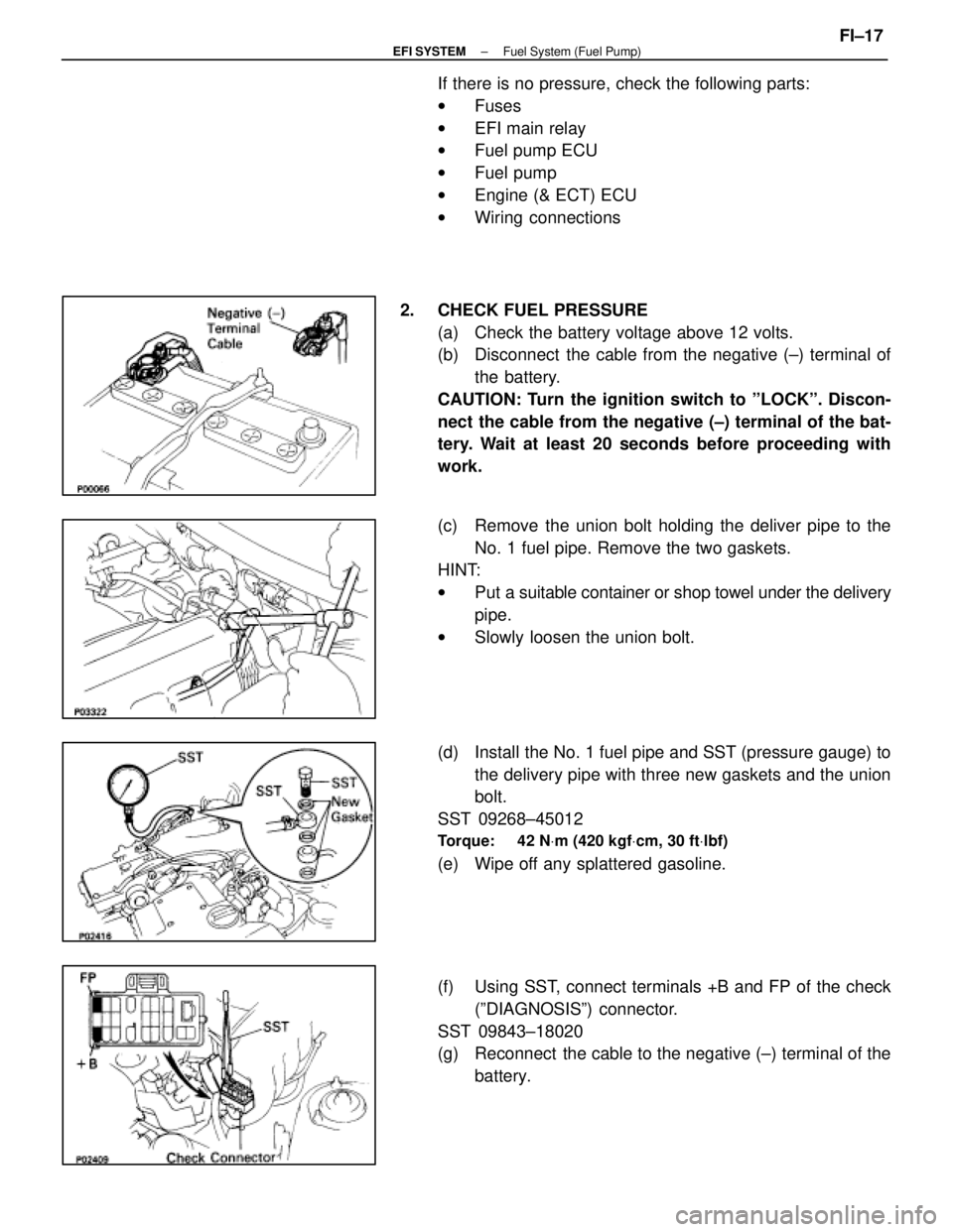
2. CHECK FUEL PRESSURE (a) Check the battery voltage above 12 volts.
(b) Disconnect the cable from the negative (±) terminal ofthe battery.
CAUTION: Turn the ignition switch to ºLOCKº. Discon-
nect the cable from the negative (±) terminal of the bat-
tery. Wait at least 20 seconds before proceeding with
work.
(c) Remove the union bolt holding the deliver pipe to the No. 1 fuel pipe. Remove the two gaskets.
HINT:
w Put a suitable container or shop towel under the delivery
pipe.
w Slowly loosen the union bolt.
(d) Install the No. 1 fuel pipe and SST (pressure gauge) to the delivery pipe with three new gaskets and the union
bolt.
SST 09268±45012
Torque: 42 N Vm (420 kgf Vcm, 30 ft Vlbf)
(e) Wipe off any splattered gasoline.
(f) Using SST, connect terminals +B and FP of the check
(ºDIAGNOSISº) connector.
SST 09843±18020
(g) Reconnect the cable to the negative (±) terminal of the battery.
±
EFI SYSTEM Fuel System (Fuel Pump)FI±17
WhereEverybodyKnowsYourName
Page 2037 of 4087

If there is no pressure, check the following parts:w Fuses
w EFI main relay
w Fuel pump ECU
w Fuel pump
w Engine & ECT ECU
w Wiring connections
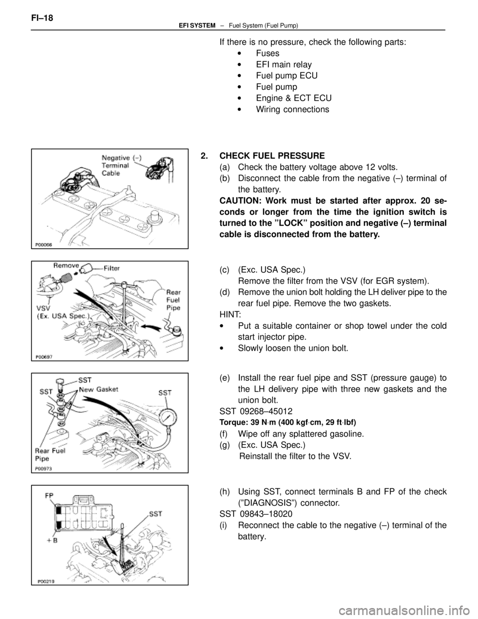
2. CHECK FUEL PRESSURE (a) Check the battery voltage above 12 volts.
(b) Disconnect the cable from the negative (±) terminal ofthe battery.
CAUTION: Work must be started after approx. 20 se-
conds or longer from the time the ignition switch is
turned to the ºLOCKº position and negative (±) terminal
cable is disconnected from the battery.
(c) (Exc. USA Spec.) Remove the filter from the VSV (for EGR system).
(d) Remove the union bolt holding the LH deliver pipe to the
rear fuel pipe. Remove the two gaskets.
HINT:
w Put a suitable container or shop towel under the cold
start injector pipe.
w Slowly loosen the union bolt.
(e) Install the rear fuel pipe and SST (pressure gauge) to the LH delivery pipe with three new gaskets and the
union bolt.
SST 09268±45012
Torque: 39 N Vm (400 kgf Vcm, 29 ft Vlbf)
(f) Wipe off any splattered gasoline.
(g) (Exc. USA Spec.)
Reinstall the filter to the VSV.
(h) Using SST, connect terminals B and FP of the check (ºDIAGNOSISº) connector.
SST 09843±18020
(i) Reconnect the cable to the negative (±) terminal of the
battery.
FI±18
EFI SYSTEM
± Fuel System (Fuel Pump)
WhereEverybodyKnowsYourName
Page 2063 of 4087
Injectors
ON±VEHICLE INSPECTION
1. INSPECT INJECTOR OPERATIONCheck operation sound from each injector.
(a) With the engine running or cranking, use a stethescopeto check that there is normal operating noise in
proportion to engine rpm.
(b) If you have no stethescope, you can check the injector transmission operation with your finger.
If no sound or an unusual sound is heard, check the wiring
connector, injector or injection signal from the ECU.
2. INSPECT INJECTOR RESISTANCE (a) Disconnect the injector connector.
(b) Using an ohmmeter, measure the resistance betweenthe terminals.
Resistance: 13.4±14.2 � at 20 5C (68 5F)
If the resistance is not as specified, replace the injector.
(c) Reconnect the injector connector.
FI±26
±
EFI SYSTEM Fuel System (Injectors)
WhereEverybodyKnowsYourName