Page 1124 of 4087
WIRING DIAGRAM
BR0F6±01
±
BRAKE SYSTEM TRACTION CONTROL SYSTEM (TRAC)BR±155
WhereEverybodyKnowsYourName
Page 1138 of 4087

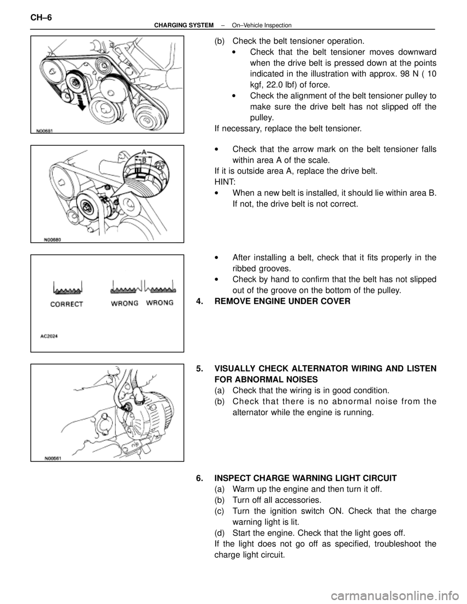
(b) Check the belt tensioner operation.w Check that the belt tensioner moves downward
when the drive belt is pressed down at the points
indicated in the illustration with approx. 98 N ( 10
kgf, 22.0 lbf) of force.
w Check the alignment of the belt tensioner pulley to
make sure the drive belt has not slipped off the
pulley.
If necessary, replace the belt tensioner.
w Check that the arrow mark on the belt tensioner falls
within area A of the scale.
If it is outside area A, replace the drive belt.
HINT:
w When a new belt is installed, it should lie within area B.
If not, the drive belt is not correct.
w After installing a belt, check that it fits properly in the
ribbed grooves.
w Check by hand to confirm that the belt has not slipped
out of the groove on the bottom of the pulley.
4. REMOVE ENGINE UNDER COVER
5. VISUALLY CHECK ALTERNATOR WIRING AND LISTEN FOR ABNORMAL NOISES
(a) Check that the wiring is in good condition.
(b) C h e c k t h a t t h e r e i s n o a bnormal noise from the
alternator while the engine is running.
6. INSPECT CHARGE WARNING LIGHT CIRCUIT (a) Warm up the engine and then turn it off.
(b) Turn off all accessories.
(c) Turn the ignition switch ON. Check that the charge
warning light is lit.
(d) Start the engine. Check that the light goes off.
If the light does not go off as specified, troubleshoot the
charge light circuit.
CH±6
±
CHARGING SYSTEM On±Vehicle Inspection
WhereEverybodyKnowsYourName
Page 1215 of 4087

Manual NamePub. No.
� SC400 Repair Manual
� SC400 Electrical Wiring Diagrar's
Manual
� Fundamental Painting Procedures
� Fundamental Body Repair Procedures BRM019U
BRM020U
M/Y Version
M/Y Version
FOREWORD
This
repair manual has been prepared to provide information on
the repair methods (including cutting and welding operations,
but excluding painting) for collision- damaged body compo-
nents of the LEXUS SC400.
Applicable models: UZZ30 series
This manual consists of body repair methods, exploded dia-
grams and illustrations of the body components and other infor-
mation relating to body panel replacement such as handling
precautions, etc. However, it should be noted that the front fend-
ers of the LEXUS model is bolted on and require no welding.
For the repair procedures and specifications other than colli-
sion-damaged body components of the LEXUS SC400 refer to
the following repair manuals.
If you require the above manuals, please contact your LEXUS
Dealer.
All information contained in this manual is the most up-to-date
at the time of publication. However, specifications and proce-
dures are subject to change without prior notice.
TOYOTA MOTOR CORPORATION
WhereEverybodyKnowsYourName
Page 1323 of 4087

INSPECTION OF COOLING FAN ECU
1. DISCONNECT CABLE FROM NEGATIVE TERMINAL OFBATTERY
CAUTION: Work must be started after 20 seconds or longer
from the time the ignition switch is turned to the ºLOCKº posi-
tion and the negative (±) terminal cable is disconnected from
the battery.
2. DISCONNECT COOLING FAN ECU CONNECTOR (See Components on page CO±60)
(a) Remove the instrument panel under cover.
(b) Remove the lower instrument panel finish panel and glove compartment door assembly.
(c) Disconnect the cooling fan ECU connector.
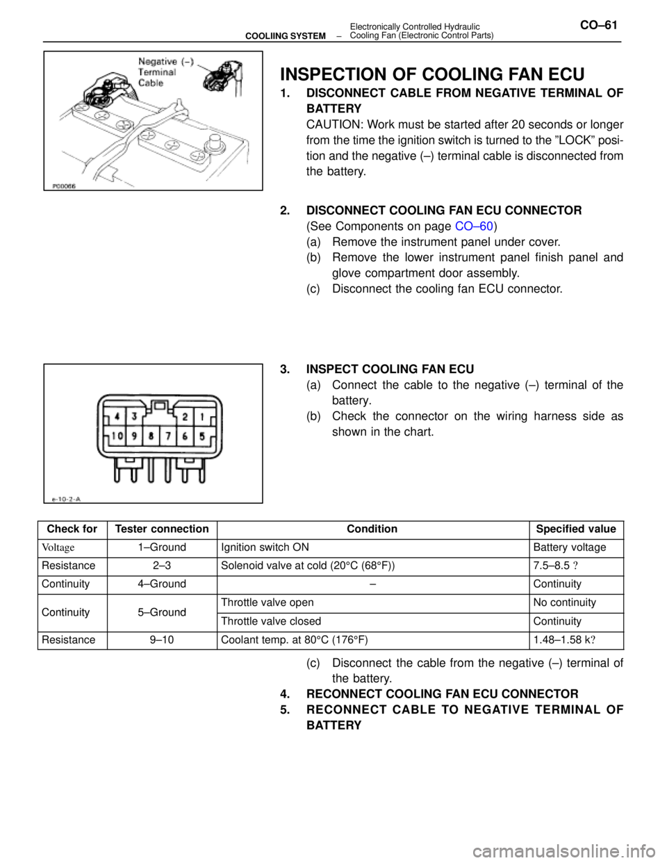
3. INSPECT COOLING FAN ECU (a) Connect the cable to the negative (±) terminal of thebattery.
(b) Check the connector on the wiring harness side as shown in the chart.
Check forTester connectionConditionSpecified value
Voltage1±GroundIgnition switch ONBattery voltage
Resistance2±3Solenoid valve at cold (20 5C (68 5F))7.5±8.5 �
Continuity4±Ground±Continuity
Continuity5±GroundThrottle valve openNo continuityContinuity5±GroundThrottle valve closedContinuity
Resistance9±10Coolant temp. at 80 5C (176 5F)1.48±1.58 k �
(c) Disconnect the cable from the negative (±) terminal of
the battery.
4. RECONNECT COOLING FAN ECU CONNECTOR
5. RECONNECT CABLE TO NEGATIVE TERMINAL OF BATTERY
±
COOLIING SYSTEM Electronically Controlled Hydraulic
Cooling Fan (Electronic Control Parts)CO±61
WhereEverybodyKnowsYourName
Page 1410 of 4087

EG115±06
IDLE SPEED INSPECTION
1. INITIAL CONDITIONS
(a) Engine at normal operating temperature
(b) Air cleaner installed
(c) All pipes and hoses of air induction system connected
(d) All accessories switched OFF
(e) All vacuum lines properly connectedHINT: All vacuum hoses for EGR system, etc. should be prop-
erly connected.
(f) MFI system wiring connectors fully plugged
(g) Ignition timing set correctly
(h) Transmission in neutral position
2. CONNECT TACHOMETER Connect the tester probe of a tachometer to terminal IG � of
the DLC1.
HINT: Set the tachometer to the 4±cylinder range.
NOTICE:
w Never allow the tachometer terminal to touch ground as
it could result in damage to the igniter and/or ignition
coil.
w As some tachometers are not compatible with this
ignition system, we recommend that you confirm the
compatibility of your unit before use.
3. INSPECT IDLE SPEED
(a) Race the engine speed at 2,500 rpm for approx. 90 seconds.
(b) Check the idle speed.
Idle speed:
700 + 50 rpm
If the idle speed is not as specified, check the IAC valve.
4. DISCONNECT TACHOMETER
EG±34
±
1UZ±FE ENGINE ENGINE MECHANICAL
WhereEverybodyKnowsYourName
Page 1411 of 4087

IDLE AND/OR 2,500 RPM CO/HC
CHECK
EG116±05
HINT: This check is used only to determine whether or not the
idle CO/HC complies with regulations.
1. INITIAL CONDITIONS
(a) Engine at normal operating temperature
(b) Air cleaner installed
(c) All pipes and hoses of air induction system connected
(d) All accessories switched OFF
(e) All vacuum lines properly connected
HINT: All vacuum hoses for EGR system, etc. should be prop-
erly connected.
(f) MFI system wiring connectors fully plugged
(g) Ignition timing set correctly
(h) Transmission in neutral position
(i) Tachometer and CO/HC meter calibrated by hand
2. START ENGINE
3. RACE ENGINE AT 2,500 RPM FOR APPROX. 180 SECONDS
4. INSERT CO/HC METER TESTING PROBE INTO TAILPIPE AT LEAST 40 cm (1.3 ft) DURING IDLING
5. IMMEDIATTELY CHECK CO/HC CONCENTRATION AT
IDLE AND/OR 2,500 RPM
HINT: When performing the 2 mode (2,500 rpm and idle) test,
follow the measurement order prescribed by the applicable
local regulations.
±
1UZ±FE ENGINE ENGINE MECHANICALEG±35
WhereEverybodyKnowsYourName
Page 1525 of 4087
36. DISCONNECT TRANSMISSION CONTROL ROD FROMSHIFT LEVER
Remove the nut, and disconnect the control rod from the shift
lever.
37. REMOVE ENGINE AND TRANSMISSION A SSEMBLY
FROM VEHICLE
(a) Attach the engine chain hoist to the engine hangers.
(b) Remove the 2 nuts holding the engine mounting insulators to
the front suspension crossmember.
(c) Remove the 4 bolts, 4 nuts and rear engine m ounting
member. Disconnect the ground strap.
(d) Lift the engine out of the vehicle slowly and carefully. HINT: Make sure the engine is clear of all wirings, hoses and
cables.
NOTICE: Be careful not hit the PS gear housing, PNP switch
and ABS actuator.
(e) Place the engine and transmission assembly onto the stand.
±
1UZ±FE ENGINE ENGINE MECHANICALEG±149
WhereEverybodyKnowsYourName
Page 1593 of 4087
35. DISCONNECT TRANSMISSION CONTROL RODRemove the nut, and disconnect the control rod from the shift
lever.
36. REMOVE ENGINE AND TRANSMISSION A SSEMBLY
FROM VEHICLE
(a) Attach the engine hoist chain to the engine hangers.
(b) Remove the two nuts holding the engine mounting insulators to the front suspension crossmember.
(c) Remove the four bolts, four nuts and rear engine mounting member. Disconnect the ground strap.
(d) Lift the engine out of the vehicle slowly and carefully.
NOTICE: Be careful not to hit the PS gear housing, neu-
tral start switch and ABS actuator.
(e) Make sure the engine is clear of all wiring, hoses and cables.
(f) Place the engine and transmission assembly onto the stand.
EM±128
±
ENGINE MECHANICAL Cylinder Block
WhereEverybodyKnowsYourName