Page 1687 of 4087

IDLE AND/OR 2,500 RPM CO/HC
CHECK
HINT: This check is used only to determine whether or not the
idle CO/HC complies with regulations.
1. INITIAL CONDITIONS (a) Engine at normal operating temperature.
(b) Air cleaner installed.
(c) All pipes and hoses of air induction system connected.
(d) All accessories switched OFF.
(e) All vacuum lines properly connected.
HINT: All vacuum hoses for EGR systems, etc. should be
properly connected.
(f) SFI system wiring connectors fully plugged.
(g) Transmission in neutral.
(h) Tachometer and CO/HC analyzer calibrated and athand.
2. START ENGINE
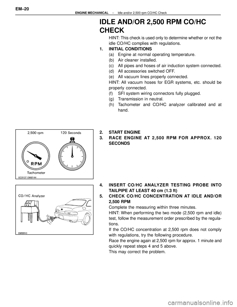
3. RACE ENGINE AT 2,500 RPM FOR APPROX. 120 SECONDS
4. INSERT CO/HC ANALYZER TESTING PROBE INTO TAILPIPE AT LEAST 40 cm (1.3 ft)
5. CHECK CO/HC CONCENTRATION AT IDLE AND/OR
2,500 RPM
Complete the measuring within three minutes.
HINT: When performing the two mode (2,500 rpm and idle)
test, follow the measurement order prescribed by the regula-
tions.
If the CO/HC concentration at 2,500 rpm does not comply
with regulations, try the following procedure.
Race the engine again at 2,500 rpm for approx. 1 minute and
quickly repeat steps 4 and 5 above.
This may correct the problem.
EM±20
±
ENGINE MECHANICAL Idle and/or 2,500 rpm CO/HC Check
WhereEverybodyKnowsYourName
Page 1701 of 4087

IDLE AND/OR 2,500 RPM HC/CO
CONCENTRATION CHECK METHOD
HINT: This check is used only to determine whether or not the
idle HC/CO complies with regulations.
1. INTIAL CONDITIONS (a) Engine at normal operating temperature.
(b) Air cleaner installed.
(c) All pipes and hoses of air induction system connected.
(d) All accessories switched OFF.
(e) All vacuum lines properly connected.
HINT: All vacuum hoses for EGR systems, etc. should be
properly connected.
(f) EFI system wiring connectors fully plugged.
(g) Transmission in neutral range.
(h) Tachometer and HC/CO meter calibrated at hand.
2. START ENGINE
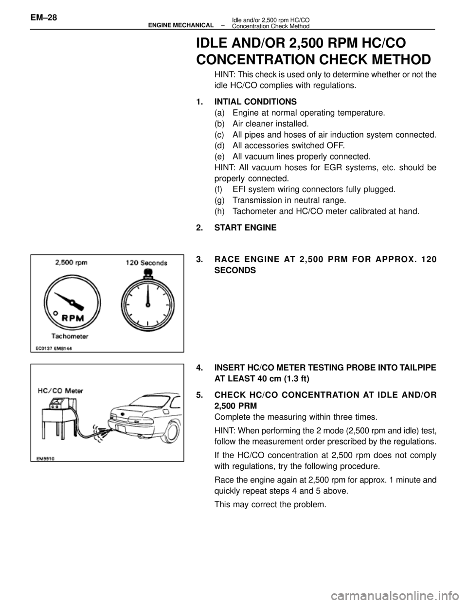
3. RACE ENGINE AT 2,500 PRM FOR APPROX. 120 SECONDS
4. INSERT HC/CO METER TESTING PROBE INTO TAILPIPE AT LEAST 40 cm (1.3 ft)
5. CHECK HC/CO CONCENTRATION AT IDLE AND/OR 2,500 PRM
Complete the measuring within three times.
HINT: When performing the 2 mode (2,500 rpm and idle) test,
follow the measurement order prescribed by the regulations.
If the HC/CO concentration at 2,500 rpm does not comply
with regulations, try the following procedure.
Race the engine again at 2,500 rpm for approx. 1 minute and
quickly repeat steps 4 and 5 above.
This may correct the problem.
EM±28
±
ENGINE MECHANICAL Idle and/or 2,500 rpm HC/CO
Concentration Check Method
WhereEverybodyKnowsYourName
Page 1827 of 4087
(b) Place the matchmarks on the both flanges.
(c) Remove the four bolts, washers, nuts and intermediateshaft.
(d) Insert SST in transmission to prevent oil leakage.
SST 09325±20010 (M/T)
09325±40010 (A/T)
21. REMOVE ENGINE AND T RANSMISSION ASSEMBLY
FROM VEHICLE
(a) Attach the engine hoist chain to the engine hangers.
(b) Remove the two nuts holding the engine to the front suspension crossmember.
(c) Remove the four bolts, four nuts and rear engine mounting member.
(d) Lift the engine out of the vehicle slowly and carefully.
NOTICE: Remove carefully without damaging the power
steering gear housing or the park/neutral position switch
(A/T only).
(e) Make sure the engine is clear of all wiring, hoses and cables.
(f) Place the engine and transmission assembly onto the
stand.
EM±72
±
ENGINE MECHANICAL Cylinder Block
WhereEverybodyKnowsYourName
Page 1885 of 4087
Idle Speed Control (ISC) Valve
ON±VEHICLE INSPECTION
INSPECT ISC VALVE FOR OPERATING SOUNDCheck that there is a clicking sound immediately after stop-
ping the engine.
If the rpm operation is not as specified, check the ISC valve,
wiring and ECU.
±
EFI SYSTEM Air Induction System (Idle Speed Control (ISC) Valve)FI±53
WhereEverybodyKnowsYourName
Page 1931 of 4087
Idle Speed Control (ISC) Valve
ON±VEHICLE INSPECTION
INSPECT ISC VALVE FOR OPERATING SOUNDCheck that there is a clicking sound immediately after stop-
ping the engine.
If the rpm operation is not as specified, check the ISC valve,
wiring and ECU.
FI±80
± Air Induction System (Idle Speed Control (ISC\
) Valve)EFI SYSTEM
WhereEverybodyKnowsYourName
Page 1937 of 4087
5. INSPECT FUEL PUMP ECU(a) Connect the cable to the negative (±) terminal of thebattery.
(b) Check the connector on the wiring harness side as shown in the chart.
Check forTester connectionConditionSpecified value
ContinuityE±Ground±Continuity
ContinuityDI±Ground±Continuity
VoltageFP GroundSudden racing12±14 VVoltageFP±GroundIdling8±10 V
Voltage+B±GroundIG SW ON8±16 V
VoltageFPC±Ground
Sudden racing
(6,000 rpm or more)4±6 VVoltageFPC Ground
Idling2.5 V
If circuit is as specified, replace the fuel pump ECU.
(c) Disconnect the cable from the negative (±) terminal of the battery.
6. RECONNECT FUEL PUMP ECU CONNECTOR
7. INSTALL QUARTER TRIM (a) Attach the upper side of the quarter trim to the quarterpanel.
(b) Install the quarter trim with the four clips.
±
EFI SYSTEM Electronic Control System (Fuel pump ECU)FI±83
WhereEverybodyKnowsYourName
Page 1974 of 4087
4. REMOVE CUP HOLDERUsing a screwdriver, pry out the rear side of the cup holder.
Remove the cup holder.
5. REMOVE UPPER REAR CONSOLE PANEL Using a screwdriver, pry out the console panel.
6. REMOVE UPPER CONSOLE PANEL (a) Remove the six mounting screws.
(b) Using a screwdriver, pry out the console panel.
7. REMOVE RADIO (a) Remove the five mounting bolts.
(b) Disconnect the wiring connectors and antenna cable,
and remove the radio.
8. DISCONNECT SUB±OXYGEN SENSOR CONNECTORS FI±119
EFI SYSTEM
± Electronic Control System (Sub±Oxygen Sensors)
WhereEverybodyKnowsYourName
Page 1975 of 4087
9. INSPECT HEATER RESISTANCE OF SUB±OXYGEN
SENSORS
Using an ohmmeter, measure the resistance between the ter-
minals +B and HT.
Resistance: 5.1±6.3 � at 20 °C (68 °F)
If the resistance is not as specified, replace the sensor as
follows:
w Disconnect the grommet from the floor panel, and
pull out the wire of the sub±oxygen sensor from the
floor panel.
w Remove the sub±oxygen sensor.
w Install a new sub±oxygen sensor.
Torque: 44 N Vm (450 kgf Vcm, 33 ft Vlbf)
w Run the wire of the sub±oxygen sensor through the
hole in the floor panel.
10. RECONNECT SUB±OXYGEN SENSOR CONNECTORS
11. REINSTALL RADIO (a) Connect the wiring connectors and antenna cable.
(b) Install the radio with the five bolts.
12. REINSTALL UPPER REAR CONSOLE PANEL (a) Fit the console panel to the console box with five clips.
(b) Install the console panel with the six screws.
FI±120
EFI SYSTEM
± Electronic Control System (Sub±Oxygen Sensors)
WhereEverybodyKnowsYourName