Page 2729 of 4087

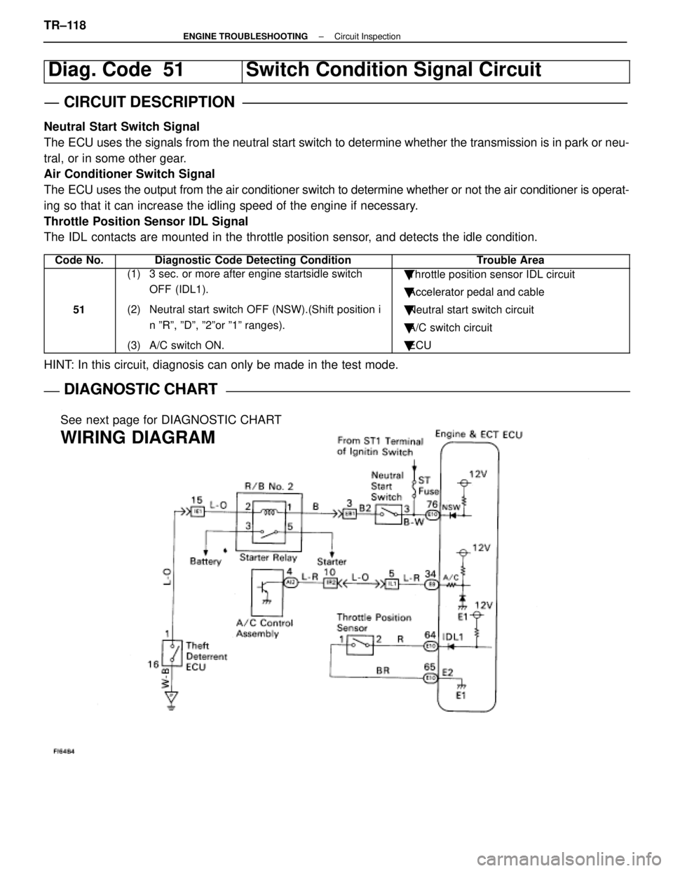
Diag. Code 51Switch Condition Signal Circuit
CIRCUIT DESCRIPTION
Neutral Start Switch Signal
The ECU uses the signals from the neutral start switch to determine whether\
the transmission is in park or neu-
tral, or in some other gear.
Air Conditioner Switch Signal
The ECU uses the output from the air conditioner switch to determine whethe\
r or not the air conditioner is operat-
ing so that it can increase the idling speed of the engine if necessary.
Throttle Position Sensor IDL Signal
The IDL contacts are mounted in the throttle position sensor, and detects the idle condition.
Code No.Diagnostic Code Detecting ConditionTrouble Area
51
(1) 3 sec. or more after engine startsidle switch OFF (IDL1).
(2) Neutral start switch OFF (NSW).(Shift position i n ºRº, ºDº, º2ºor º1º ranges).
(3) A/C switch ON.� Throttle position sensor IDL circuit
� Accelerator pedal and cable
� Neutral start switch circuit
� A/C switch circuit
� ECU
HINT: In this circuit, diagnosis can only be made in the test mode.
DIAGNOSTIC CHARTDIAGNOSTIC CHART
See next page for DIAGNOSTIC CHART
WIRING DIAGRAM
TR±118±
ENGINE TROUBLESHOOTING Circuit Inspection
WhereEverybodyKnowsYourName
Page 2735 of 4087
ECU Power Source Circuit
CIRCUIT DESCRIPTION
When the ignition switch is turned on, battery voltage
is applied to the terminal IG SW of the ECU, and the
main relay control circuit in the ECU sends a signal to
the terminal M±REL of the ECU, switching on the
main relay. This signal causes current to flow to the
coil, closing the contacts of the main relay and supply-
ing power to the terminals +B and +B1 of the ECU.
If the ignition switch is turned off, the ECU continues
to switch on the main relay for a maximum of 2 se-
conds for the initial setting of the ISC valve.
DIAGNOSTIC CHARTDIAGNOSTIC CHART
See next page for the DIAGNOSTIC CHART.
WIRING DIAGRAM
TR±124±
ENGINE TROUBLESHOOTING Circuit Inspection
WhereEverybodyKnowsYourName
Page 2738 of 4087
OKNG
OKNG
4Check IGN Fuse.
C
OK
PRemove IGN fuse from J/B No.1.
Check continuity of IGN fuse.
Continuity.
Check for short in all the harness and components con-
nected to IGN fuse (See attached wiring diagram).
5Check ignition switch.
C
OK
PRemove under cover and finish panel.
Check continuity between terminals.
continuity
Replace ignition switch.
Check and repair harness and connector between
battery and ignition switch, ignition switch and en-
gine & ECT ECU.
±
ENGINE TROUBLESHOOTING Circuit InspectionTR±127
WhereEverybodyKnowsYourName
Page 2741 of 4087
Back Up Power Source Circuit
CIRCUIT DESCRIPTION
Battery voltage is supplied to terminal BATT of the ECU even when the ignition switch is off for use by
the diagnostic code memory and air±fuel ratio adaptive control value mem\
ory, etc.
DIAGNOSTIC CHARTDIAGNOSTIC CHART
Check for short in all the harness and
components connected to EFI fuse.Check EFI fuse.
Check of terminal BATT.
Proceed to next circuit inspection shown on
matrix chart (See page TR±35).
Check operation for the back up.Check and replace ECU.
Check and repair harness or connector
between battery, EFI fuse and ECU.
WIRING DIAGRAM
TR±130±
ENGINE TROUBLESHOOTING Circuit Inspection
WhereEverybodyKnowsYourName
Page 2742 of 4087
OKNG
OKNG
YESNO
INSPECTION PROCEDURE
1Check EFI fuse.
C
OK
PRemove EFI fuse from R/B No.2.
Check continuity of EFI fuse.
Continuity
Check for short in all the harness and components con-
nected to EFI fuse (See attached wiring diagram).
2Check voltage between terminal BATT of engine & ECT ECU connector and body ground.
C
OK
PConnect the Check Harness A.
(See page TR±30).
Measure voltage between terminal BATT of engine &
ECT ECU connector and body ground.
Voltage: 10 ± 14 V
Check and repair harness or connector between engine
& ECT ECU and EFI fuse, EFI fuse and battery.
3Are the diagnostic codes still in the memory when the ignition switch is\
turned OFF?
Check and replace engine & ECT ECU.
Proceed to next circuit inspection shown on ma-
trix chart (See page TR±35).
±
ENGINE TROUBLESHOOTING Circuit InspectionTR±131
WhereEverybodyKnowsYourName
Page 2744 of 4087
WIRING DIAGRAM
±
ENGINE TROUBLESHOOTING Circuit InspectionTR±133
WhereEverybodyKnowsYourName
Page 2748 of 4087
DIAGNOSTIC CHART
DIAGNOSTIC
CHART
Check voltage of cold start injector power
source.
Check cold start injector.
Check start injector time switch.Replace start injector time switch.
Repair or replace harness or
connector.
Replace cold start injector.
Check for open and short in harness and
connector between cold start injector and
start injector time switch.
Check fuel injection of cold start injector.
Proceed to next circuit inspection shown on
matrix chart (See page TR±35).
Check for open in harness and connector
between battery and ECU.
Replace cold start injector.
WIRING DIAGRAM
±
ENGINE TROUBLESHOOTING Circuit InspectionTR±137
WhereEverybodyKnowsYourName
Page 2753 of 4087
Fuel Pressure Control VSV Circuit
CIRCUIT DESCRIPTION
The ECU turns on a VSV (Vacuum Switching Valve)
to draw the air into the diaphragm chamber of the
pressure regulator if it detects that the temperature of
the coolant is too high during engine starting.
The air drawn into the chamber increases the fuel
pressure to prevent fuel vapor lock at high engine
temperature in order to help the engine start when it
is warm.
Fuel pressure control ends approx. 100 secs. after
the engine is started.
DIAGNOSTIC CHARTDIAGNOSTIC CHART
Check operation for fuel pressure control
VSV.Replace fuel pressure control VSV.
Repair or replace harness or
connector.
Proceed to next circuit inspection
shown on matrix chart (See page
TR±35).
Check for open and short in harness and
connector between main relay and ECU.
Check voltage of VSV power source.
Check and replace ECU.
WIRING DIAGRAM
TR±142±
ENGINE TROUBLESHOOTING Circuit Inspection
WhereEverybodyKnowsYourName