Page 3086 of 4087
OKNG
3Check DOME Fuse.
C
OK
PRemove DOME Fuse from R/B No. 2.
Check continuity of DOME Fuse.
Continuity
Check for short in all the harness and components con-
nected to DOME Fuse (See attached wiring diagram).
Check harness and connector between ECU and
battery (See page
IN±33).
SR±64±
STEERING STEERING COLUMN
WhereEverybodyKnowsYourName
Page 3089 of 4087
WIRING DIAGRAM
DIAGNOSTIC CHARTDIAGNOSTIC CHART
±
SUPPLEMENTAL RESTRAINT SYSTEM TROUBLESHOOTINGRS±111
WhereEverybodyKnowsYourName
Page 3094 of 4087
WIRING DIAGRAM
DIAGNOSTIC CHARTDIAGNOSTIC CHART
RS±116±
SUPPLEMENTAL RESTRAINT SYSTEM TROUBLESHOOTING
WhereEverybodyKnowsYourName
Page 3096 of 4087

OKNG
OKNG
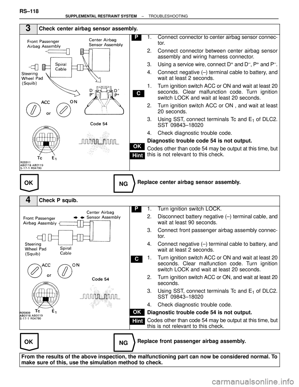
3Check center airbag sensor assembly.
C
OK
Hint
P1. Connect connector to center airbag sensor connec-
tor.
2. Connect connector between center airbag sensor assembly and wiring harness connector.
3. Using a service wire, connect D
+ and D±, P+ and P±.
4. Connect negative (±) terminal cable to battery, and wait at least 2 seconds.
1. Turn ignition switch ACC or ON and wait at least 20 seconds. Clear malfunction code. Turn ignition
switch LOCK and wait at least 20 seconds.
2. Turn ignition switch ACC or ON , and wait at least 20 seconds.
3. Using SST, connect terminals Tc and E
1 of DLC2.
SST 09843±18020
4. Check diagnostic trouble code.
Diagnostic trouble code 54 is not output.
Codes other t han code 54 may be output at this time, but
this is not relevant to this check.
Replace center airbag sensor assembly.
4Check P squib.
C
OK
Hint
P1. Turn ignition switch LOCK.
2. Disconnect battery negative (±) terminal cable, and
wait at least 90 seconds.
3. Connect front passenger airbag assembly connec- tor.
4. Connect negative (±) terminal cable to battery, and wait at least 2 seconds.
1. Turn ignition switch ACC or ON and wait at least 20 seconds. Clear malfunction code. Turn ignition
switch LOCK and wait at least 20 seconds.
2. Turn ignition switch ACC or ON, and wait at least 20
seconds.
3. Using SST, connect terminals Tc and E
1 of DLC2.
SST 09843±18020
4. Check diagnostic trouble code.
Diagnostic trouble code 54 is not output.
Codes other t han code 54 may be output at this time, but
this is not relevant to this check.
Replace front passenger airbag assembly.
From the results of the above inspection, the malfunctioning part can now be\
considered normal. To
make sure of this, use the simulation method to check.
RS±118±
SUPPLEMENTAL RESTRAINT SYSTEM TROUBLESHOOTING
WhereEverybodyKnowsYourName
Page 3097 of 4087
WIRING DIAGRAM
SRS Warning Light System (Always Lit Up, when ignition switch in
LOCK position)
CIRCUIT DESCRIPTION
The SRS warning light is located on the combination meter.
When the supplemental restraint system is normal, the SRS warning light ligh\
ts up for approx. 6 seconds after
the ignition switch is turned from LOCK position to ACC or ON position, and\
then turns off automatically.
If there is a malfunction in the supplemental restraint system, the SRS wa\
rning light lights up to inform the driver
of the abnormality.
When terminals Tc and E
1 of the DLC2 are connected, the diagnostic trouble code is displayed by \
the blinking
of the SRS warning light.
DIAGNOSTIC CHARTDIAGNOSTIC CHART
HINT: If the SRS warning light is always lit up by a DTC check procedure, per\
form Tc T erminal circuit check proce-
dure (See page RS±121).
±
SUPPLEMENTAL RESTRAINT SYSTEM TROUBLESHOOTINGRS±119
WhereEverybodyKnowsYourName
Page 3100 of 4087
WIRING DIAGRAM
DIAGNOSTIC CHARTDIAGNOSTIC CHART
RS±122±
SUPPLEMENTAL RESTRAINT SYSTEM TROUBLESHOOTING
WhereEverybodyKnowsYourName
Page 3111 of 4087
RSOOU±02
WIRING DIAGRAM
±
SUPPLEMENTAL RESTRAINT SYSTEM DESCRIPTIONRS±7
WhereEverybodyKnowsYourName
Page 3122 of 4087
COMPONENTS
RS04D±01
STEERING WHEEL PAD AND SPIRAL
CABLE REMOVAL AND INSTALLATION
RS04D±01
NOTICE:
wIf the wiring connector of the supplemental restraint
system is disconnected with the ignition switch at ON or
ACC, diagnostic trouble codes will be recorded.
w Never use SRS parts from another vehicle. When
replacing parts, replace with new parts.
1. DISCONNECT NEGATIVE (±) TERMINAL CABLE FROM
BATTERY
CAUTION: Work must be started after 90 seconds from
the time the ignition switch is turned to the LOCK posi-
tion and the negative (±) terminal cable is disconnected
from the battery (See page RS±2).
RS±18
±
SUPPLEMENTAL RESTRAINT SYSTEM STEERING WHEEL PAD AND SPIRAL CABLE
WhereEverybodyKnowsYourName