Page 3353 of 4087
WIRING DIAGRAM
±
ENGINE TROUBLESHOOTING Circuit InspectionTR±129
WhereEverybodyKnowsYourName
Page 3356 of 4087
Back Up Power Source Circuit
CIRCUIT DESCRIPTION
Battery voltage is supplied to terminal BATT of the ECU even when the ignition switch is off for use by
the diagnostic code memory and air±fuel ratio adaptive control value mem\
ory, etc.
DIAGNOSTIC CHARTDIAGNOSTIC CHART
Check for short in all the harness and
components connected to EFI fuse.Check EFI fuse.
Check of terminal BATT.
Proceed to next circuit inspection shown on
matrix chart (See page TR±35).
Check operation for the back up.Check and replace ECU.
Check and repair harness or connector
between battery, EFI fuse and ECU.
WIRING DIAGRAM
TR±130±
ENGINE TROUBLESHOOTING Circuit Inspection
WhereEverybodyKnowsYourName
Page 3357 of 4087
OKNG
OKNG
YESNO
INSPECTION PROCEDURE
1Check EFI fuse.
C
OK
PRemove EFI fuse from R/B No.2.
Check continuity of EFI fuse.
Continuity
Check for short in all the harness and components con-
nected to EFI fuse (See attached wiring diagram).
2Check voltage between terminal BATT of engine & ECT ECU connector and body ground.
C
OK
PConnect the Check Harness A.
(See page TR±30).
Measure voltage between terminal BATT of engine &
ECT ECU connector and body ground.
Voltage: 10 ± 14 V
Check and repair harness or connector between engine
& ECT ECU and EFI fuse, EFI fuse and battery.
3Are the diagnostic codes still in the memory when the ignition switch is\
turned OFF?
Check and replace engine & ECT ECU.
Proceed to next circuit inspection shown on ma-
trix chart (See page TR±35).
±
ENGINE TROUBLESHOOTING Circuit InspectionTR±131
WhereEverybodyKnowsYourName
Page 3359 of 4087
WIRING DIAGRAM
±
ENGINE TROUBLESHOOTING Circuit InspectionTR±133
WhereEverybodyKnowsYourName
Page 3363 of 4087
DIAGNOSTIC CHART
DIAGNOSTIC
CHART
Check voltage of cold start injector power
source.
Check cold start injector.
Check start injector time switch.Replace start injector time switch.
Repair or replace harness or
connector.
Replace cold start injector.
Check for open and short in harness and
connector between cold start injector and
start injector time switch.
Check fuel injection of cold start injector.
Proceed to next circuit inspection shown on
matrix chart (See page TR±35).
Check for open in harness and connector
between battery and ECU.
Replace cold start injector.
WIRING DIAGRAM
±
ENGINE TROUBLESHOOTING Circuit InspectionTR±137
WhereEverybodyKnowsYourName
Page 3368 of 4087
Fuel Pressure Control VSV Circuit
CIRCUIT DESCRIPTION
The ECU turns on a VSV (Vacuum Switching Valve)
to draw the air into the diaphragm chamber of the
pressure regulator if it detects that the temperature of
the coolant is too high during engine starting.
The air drawn into the chamber increases the fuel
pressure to prevent fuel vapor lock at high engine
temperature in order to help the engine start when it
is warm.
Fuel pressure control ends approx. 100 secs. after
the engine is started.
DIAGNOSTIC CHARTDIAGNOSTIC CHART
Check operation for fuel pressure control
VSV.Replace fuel pressure control VSV.
Repair or replace harness or
connector.
Proceed to next circuit inspection
shown on matrix chart (See page
TR±35).
Check for open and short in harness and
connector between main relay and ECU.
Check voltage of VSV power source.
Check and replace ECU.
WIRING DIAGRAM
TR±142±
ENGINE TROUBLESHOOTING Circuit Inspection
WhereEverybodyKnowsYourName
Page 3372 of 4087

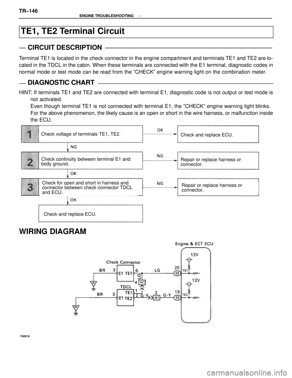
TE1, TE2 Terminal Circuit
CIRCUIT DESCRIPTION
Terminal TE1 is located in the check connector in the engine compartment and terminals T\
E1 and TE2 are lo-
cated in the TDCL in the cabin. When these terminals are connected with \
the E1 terminal, diagnostic codes in
normal mode or test mode can be read from the ºCHECKº engine warning lig\
ht on the combination meter.
DIAGNOSTIC CHARTDIAGNOSTIC CHART
HINT: If terminals TE1 and TE2 are connected with terminal E1, diagnostic code is not output or test mode isnot activated.
Even though terminal TE1 is not connected with terminal E1, the ºCHEC\
Kº engine warning light blinks.
For the above phenomenon, the likely cause is an open or short in the wire \
harness, or malfunction inside
the ECU.
Check continuity between terminal E1 and
body ground.
Repair or replace harness or
connector.Check for open and short in harness and
connector between check connector TDCL
and ECU.
Check voltage of terminals TE1, TE2.
Check and replace ECU.
Repair or replace harness or
connector.
Check and replace ECU.
WIRING DIAGRAM
TR±146±
ENGINE TROUBLESHOOTING
WhereEverybodyKnowsYourName
Page 3402 of 4087
WIRING DIAGRAM
TR±28±
ENGINE TROUBLESHOOTING Wiring Diagram
WhereEverybodyKnowsYourName