Page 2757 of 4087

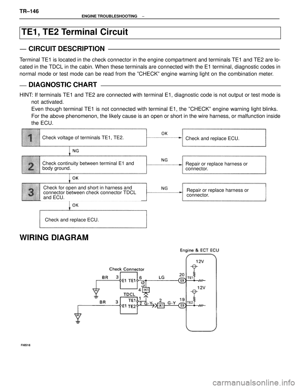
TE1, TE2 Terminal Circuit
CIRCUIT DESCRIPTION
Terminal TE1 is located in the check connector in the engine compartment and terminals T\
E1 and TE2 are lo-
cated in the TDCL in the cabin. When these terminals are connected with \
the E1 terminal, diagnostic codes in
normal mode or test mode can be read from the ºCHECKº engine warning lig\
ht on the combination meter.
DIAGNOSTIC CHARTDIAGNOSTIC CHART
HINT: If terminals TE1 and TE2 are connected with terminal E1, diagnostic code is not output or test mode isnot activated.
Even though terminal TE1 is not connected with terminal E1, the ºCHEC\
Kº engine warning light blinks.
For the above phenomenon, the likely cause is an open or short in the wire \
harness, or malfunction inside
the ECU.
Check continuity between terminal E1 and
body ground.
Repair or replace harness or
connector.Check for open and short in harness and
connector between check connector TDCL
and ECU.
Check voltage of terminals TE1, TE2.
Check and replace ECU.
Repair or replace harness or
connector.
Check and replace ECU.
WIRING DIAGRAM
TR±146±
ENGINE TROUBLESHOOTING
WhereEverybodyKnowsYourName
Page 2760 of 4087
Wiring and Connector Diagrams
Parts Inspection
(Defogger Switch)
REMOVAL AND INSTALLATION OF AIR
CONDITIONER CONTROL PANEL
ASSEMBLY
(See Instrument Panel on Pub. No. RM260U2, page BO±111)
INSPECTION OF DEFOGGER SWITCH
INSPECT SWITCH OPERATION
(a) Connect the positive (+) lead from the battery to terminal A6and negative (±) lead to terminal A7.
(b) Connect the positive (+) lead from the battery to terminal B10
through a 1.4 W test bulb.
BE±52
±
BODY ELECTRICAL SYSTEM Defogger System
WhereEverybodyKnowsYourName
Page 2770 of 4087

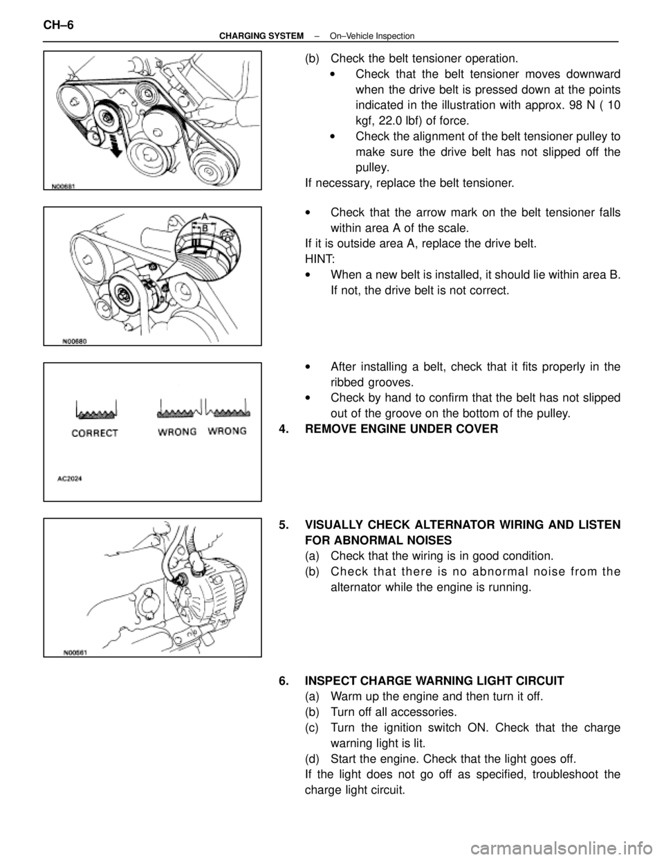
(b) Check the belt tensioner operation.w Check that the belt tensioner moves downward
when the drive belt is pressed down at the points
indicated in the illustration with approx. 98 N ( 10
kgf, 22.0 lbf) of force.
w Check the alignment of the belt tensioner pulley to
make sure the drive belt has not slipped off the
pulley.
If necessary, replace the belt tensioner.
w Check that the arrow mark on the belt tensioner falls
within area A of the scale.
If it is outside area A, replace the drive belt.
HINT:
w When a new belt is installed, it should lie within area B.
If not, the drive belt is not correct.
w After installing a belt, check that it fits properly in the
ribbed grooves.
w Check by hand to confirm that the belt has not slipped
out of the groove on the bottom of the pulley.
4. REMOVE ENGINE UNDER COVER
5. VISUALLY CHECK ALTERNATOR WIRING AND LISTEN FOR ABNORMAL NOISES
(a) Check that the wiring is in good condition.
(b) C h e c k t h a t t h e r e i s n o a bnormal noise from the
alternator while the engine is running.
6. INSPECT CHARGE WARNING LIGHT CIRCUIT (a) Warm up the engine and then turn it off.
(b) Turn off all accessories.
(c) Turn the ignition switch ON. Check that the charge
warning light is lit.
(d) Start the engine. Check that the light goes off.
If the light does not go off as specified, troubleshoot the
charge light circuit.
CH±6
±
CHARGING SYSTEM On±Vehicle Inspection
WhereEverybodyKnowsYourName
Page 2847 of 4087

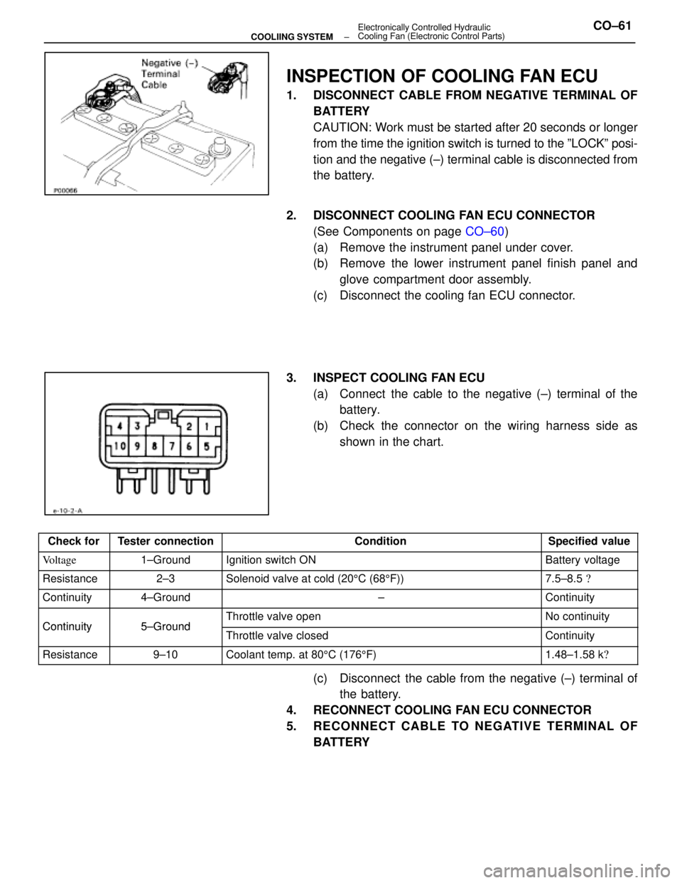
INSPECTION OF COOLING FAN ECU
1. DISCONNECT CABLE FROM NEGATIVE TERMINAL OFBATTERY
CAUTION: Work must be started after 20 seconds or longer
from the time the ignition switch is turned to the ºLOCKº posi-
tion and the negative (±) terminal cable is disconnected from
the battery.
2. DISCONNECT COOLING FAN ECU CONNECTOR (See Components on page CO±60)
(a) Remove the instrument panel under cover.
(b) Remove the lower instrument panel finish panel and glove compartment door assembly.
(c) Disconnect the cooling fan ECU connector.
3. INSPECT COOLING FAN ECU (a) Connect the cable to the negative (±) terminal of thebattery.
(b) Check the connector on the wiring harness side as shown in the chart.
Check forTester connectionConditionSpecified value
Voltage1±GroundIgnition switch ONBattery voltage
Resistance2±3Solenoid valve at cold (20 5C (68 5F))7.5±8.5 �
Continuity4±Ground±Continuity
Continuity5±GroundThrottle valve openNo continuityContinuity5±GroundThrottle valve closedContinuity
Resistance9±10Coolant temp. at 80 5C (176 5F)1.48±1.58 k �
(c) Disconnect the cable from the negative (±) terminal of
the battery.
4. RECONNECT COOLING FAN ECU CONNECTOR
5. RECONNECT CABLE TO NEGATIVE TERMINAL OF BATTERY
±
COOLIING SYSTEM Electronically Controlled Hydraulic
Cooling Fan (Electronic Control Parts)CO±61
WhereEverybodyKnowsYourName
Page 2928 of 4087
SR±52).
IN±33).
WIRING DIAGRAM
Actuator Power Source Circuit
CIRCUIT DESCRIPTION
This is the power source for the motor.
DIAGNOSTIC CHARTDIAGNOSTIC CHART
SR±66±
STEERING STEERING COLUMN
WhereEverybodyKnowsYourName
Page 2930 of 4087
OKNG
3Check PWR fusible link.
C
OK
PRemove PWR fusible link from J/B No. 1.
Check continuity of PWR fusible link.
Continuity
Check for short in all the harness and components con-
nected to the PWR fusible link (See attached wiring dia-
gram ).
Check harness and connector between ECU and
battery (See page
IN±33).
SR±68±
STEERING STEERING COLUMN
WhereEverybodyKnowsYourName
Page 2932 of 4087
SR±52).
WIRING DIAGRAM
Sensor Power Source Circuit
CIRCUIT DESCRIPTION
Power to the position sensors, manual switch and auto set switch is output fr\
om the ECU.
DIAGNOSTIC CHARTDIAGNOSTIC CHART
SR±70±
STEERING STEERING COLUMN
WhereEverybodyKnowsYourName
Page 2934 of 4087
SR±52).
IN±33).
WIRING DIAGRAM
Tilt Position Sensor Circuit
CIRCUIT DESCRIPTION
The tilt position is sent to the ECU as a voltage signal from the position \
sensor.
A constant 5 V is supplied to terminal 1 of sensor.
The voltage at terminal 3 varies with position and is input to the ECU.
DIAGNOSTIC CHARTDIAGNOSTIC CHART
SR±72±
STEERING STEERING COLUMN
WhereEverybodyKnowsYourName