Page 1533 of 4087
(d) Clean the crank pin and bearing.
(e) Check the crank pin and bearing for pitting and scratches.If the crank pin or bearing is damaged, replace the bearings.
If necessary, replace the crankshaft.
(f) Lay a strip of Plastigage across the crank pin.
(g) Install the connecting rod cap with the 2 bolts. (See step 7 on page EG±183)
Torque:
1st 25 N Vm (250 kgf Vcm, 18 ft Vlbf)
2nd Turn 90 5
NOTICE: Do not turn the crankshaft.
(h) Remove the 2 bolts, connecting rod cap and lower bearing. (See procedure (b) and (c) above)
(i) Measure the Plastigage at its widest point.
Standard oil clearance: 0.027 ± 0.053 mm (0.0011 ± 0.0021 in.)
Maximum oil clearance: 0.065 mm (0.0026 in.)
If the oil clearance is greater than maximum, replace the
bearings. If necessary, replace the crankshaft.
±
1UZ±FE ENGINE ENGINE MECHANICALEG±157
WhereEverybodyKnowsYourName
Page 1535 of 4087
4. REMOVE PISTON AND CONNECTING RODASSEMBLIES
(a) Using a ridge reamer, remove all the carbon from the top of
the cylinder.
(b) Push the piston, connecting rod assembly and upper bearing through the top of the cylinder block.
HINT:
wKeep the bearings, connecting rod and cap together.
w Arrange the piston and connecting rod assemblies in
correct order.
5. CHECK CRANKSHAFT THRUST CLEARANCE Using a dial indi cator, measure the thrust clearance while pry-
ing the crankshaft back and forth with a screwdriver.
Standard thrust clearance:
0.020 ± 0.220 mm (0.0008 ± 0.0087 in.)
Maximum thrust clearance: 0.30 mm (0.0118 in.)
If the thrust clearance is greater than maximum, replace the
thrust washers as a set.
Thrust washer thickness:2.440 ± 2.490 mm (0.0961 ± 0.0980 in.)
±
1UZ±FE ENGINE ENGINE MECHANICALEG±159
WhereEverybodyKnowsYourName
Page 1536 of 4087

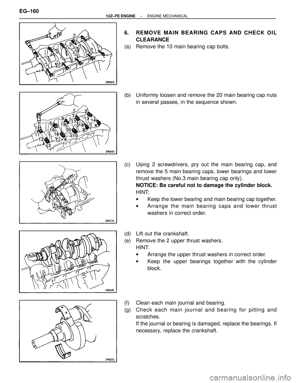
6. REMOVE MAIN BEARING CAPS AND CHECK OILCLEARANCE
(a) Remove the 10 main bearing cap bolts.
(b) Uniformly loosen and remove the 20 main bearing cap nuts
in several passes, in the sequence shown.
(c) Using 2 screwdrivers, pry out the main bearing cap, and remove the 5 main bearing caps, lower bearings and lower
thrust washers (No.3 main bearing cap only).
NOTICE: Be careful not to damage the cylinder block.
HINT:
wKeep the lower bearing and main bearing cap together.
w Arrange the main bearing caps and lower thrust
washers in correct order.
(d) Lift out the crankshaft.
(e) Remove the 2 upper thrust washers. HINT:
wArrange the upper thrust washers in correct order.
w Keep the upper bearings together with the cylinder
block.
(f) Clean each main journal and bearing.
(g) Ch e ck ea ch ma in jo u rn a l an d be a rin g fo r pittin g an d scratches.
If the journal or bearing is damaged, replace the bearings. If
necessary, replace the crankshaft.
EG±160
±
1UZ±FE ENGINE ENGINE MECHANICAL
WhereEverybodyKnowsYourName
Page 1541 of 4087
CYLINDER BLOCK INSPECTION AND
REPAIR
EG1KU±01
1. CLEAN CYLINDER BLOCK
A. Remove gasket materialUsing a gasket scraper, remove all the gasket material from
the top surface of the cylinder block.
B. Clean cylinder block
Using a soft brush and solvent, thoroughly clean the cylinder
block.
NOTICE: If the cylinder is washed at high temperatures, the
cylinder liner sticks out beyond the cylinder block, so always
wash the cylinder block at temperature of 45 � or less.
2. INSPECT TOP SURFACE OF CYLINDER BLOCK FOR
FLATNESS
Using a precision straight edge and feeler gauge, measure
the surface contacting the cylinder head gasket for warpage.
Maximum warpage:
0.07 mm (0.0028 in.)
If warpage is greater than maximum, replace the cylinder
block.
3. INSPECT CYLINDER FOR VERTICAL SCRATCHES Visually check the cylinder for vertical scratches.
If deep scratches are present, replace the cylinder block.
±
1UZ±FE ENGINE ENGINE MECHANICALEG±165
WhereEverybodyKnowsYourName
Page 1543 of 4087
7. IF NECESSARY, REPLACE MAIN BEARING CAP STUDBOLTS
(a) Using the 2 main bearing cap nuts, remove the stud bolt.
(b) Apply a light coat of engine oil on the threads and under
flange of new stud bolts.
(c) Using the 2 main bearing cap nuts, install the stud bolt.
Torque: 15 N Vm (150 kgf Vcm, 11 ft Vlbf)
HINT: Stud bolts come in lengths of 90.0 mm (3.543 in.) and
101.5 mm (3.996 in.). Install the 101.5 mm (3.996 in.) bolts
in inside positions. Install the 90.0 mm (3.543 in.) bolts in out-
side positions.
PISTON AND CONNECTING ROD
DISASSEMBLY
EG0BV±06
1. CHECK FIT BETWEEN PISTON AND PISTON PIN
Try to move the piston back and forth on the piston pin.
If any movement is felt, replace the piston and pin as a set.
2. REMOVE PISTON RINGS
(a) Using a piston ring expander, remove the 2 compression rings.
±
1UZ±FE ENGINE ENGINE MECHANICALEG±167
WhereEverybodyKnowsYourName
Page 1548 of 4087

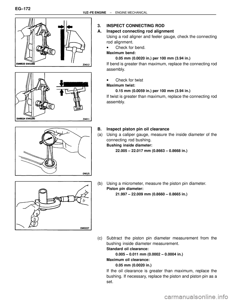
3. INSPECT CONNECTING ROD
A. Inspect connecting rod alignmentUsing a rod aligner and feeler gauge, check the connecting
rod alignment.
wCheck for bend.
Maximum bend:
0.05 mm (0.0020 in.) per 100 mm (3.94 in.)
If bend is greater than maximum, replace the connecting rod
assembly.
wCheck for twist
Maximum twist:
0.15 mm (0.0059 in.) per 100 mm (3.94 in.)
If twist is greater than maximum, replace the connecting rod
assembly.
B. Inspect piston pin oil clearance
(a) Using a caliper gauge, measure the inside diameter of the connecting rod bushing.
Bushing inside diameter:
22.005 ± 22.017 mm (0.8663 ± 0.8668 in.)
(b) Using a micrometer, measure the piston pin diameter.
Piston pin diameter:21.997 ± 22.009 mm (0.8660 ± 0.8665 in.)
(c) Subtract the piston pin diameter measurement from thebushing inside diameter measurement.
Standard oil clearance:
0.005 ± 0.011 mm (0.0002 ± 0.0004 in.)
Maximum oil clearance: 0.05 mm (0.0020 in.)
If the oil clearance is greater than maximum, replace the
bushing. If necessary, replace the piston and piston pin as a
set.
EG±172
±
1UZ±FE ENGINE ENGINE MECHANICAL
WhereEverybodyKnowsYourName
Page 1549 of 4087
C. If necessary, replace connecting rod bushing
(a) Using SST and a press, press out the bushing.SST 09222±30010
(b) Align the oil holes of a new bushing and the connecting rod.
(c) Using SST and a press, press out the bushing SST 09222±30010
(d) Using a pin hole grinder, hone the bushing to obtain the standard specified clearance (see step B above) between
the bushing and piston pin.
(e) Check the piston pin fit at normal room temperature. Coat the piston pin with engine oil, and push it into the con-
necting rod with your thumb.
D. Inspect connecting rod bolts Using a vernier caliper, measure the tension portion of of the
connecting rod bolt.
Standard diameter:
7.200 ± 7.300 mm (0.2835 ± 0.2874 in.)
Maximum diameter: 7.00 mm (0.2756 in.)
HINT: If the tension portion diameter is less than minimum,
replace the connecting rod bolt.
±
1UZ±FE ENGINE ENGINE MECHANICALEG±173
WhereEverybodyKnowsYourName
Page 1550 of 4087
CRANKSHAFT INSPECTION
EG0BY±0D
1. INSPECT CRANKSHAFT FOR CIRCLE RUNOUT
(a) Place the crankshaft on V±blocks.
(b) Using a dial indicator, measure the circle runout at the centerjournal.
Maximum circle runout:
0.08 mm (0.0031 in.)
If the circle runout is greater than maximum, replace the
crankshaft.
2. INSPECT MAIN JOURNALS AND CRANK PINS
(a) Using a micrometer, measure the diameter of each main journal and crank pin.
Main journal diameter:
66.988 ± 67.000 mm (2.6373 ± 2.6378 in.)
Crank pin diameter: 51.982 ± 52.000 mm (2.0465 ± 2.0472 in.)
If the diameter is not as specified, check the oil clearance
(See steps 3 or 6 on page EG±156 or 160). If necessary, re-
place the crankshaft.
(b) Ch e ck ea ch ma in jo u rn a l an d cra n k pin fo r t aper and
out±of±round as shown.
Maximum taper and out±of±round:
0.02 mm (0.0008 in.)
If the taper and out±of±round is greater than maximum, re-
place the crankshaft.
EG±174
±
1UZ±FE ENGINE ENGINE MECHANICAL
WhereEverybodyKnowsYourName