Page 1484 of 4087
2. INSTALL VALVES
(a) Using SST, push in a new oil seal.SST 09201±41020
(b) Install the following parts: (1) Valve
(2) Spring seat
(3) Valve spring
(4) Spring retainer
(c) Using SST, compress the valve spring and place the 2 keepers around the valve stem.
SST 09202±70010
(d) Using a plastic±faced hammer, lightly tap the valve stem tip to assure proper fit.
3. INSTALL VALVE LIFTERS AND SHIMS
(a) Install the valve lifter and shim.
(b) Check that the valve lifter rotates smoothly by hand.
EG±108
±
1UZ±FE ENGINE ENGINE MECHANICAL
WhereEverybodyKnowsYourName
Page 1488 of 4087
(e) Retighten the cylinder head bolts 90� in the numerical order
shown.
(f) Check that the painted mark is now at a 90 � angle to front.
4. CONNECT MAIN HEATED OXYGEN SENSOR CONNECTORS
Connect the RH and LH oxygen sensor connectors.
5. INSTALL CIRCULAR PLUGS
(a) Place 2 new circular plugs in position on the cylinder heads, facing the cup side forward.
(b) Remove any old packing (FIPG) material.
(c) Apply seal packing to the bearing caps as shown.
Seal packing: Part No. 08826±00080 or equivalent
EG±112±
1UZ±FE ENGINE ENGINE MECHANICAL
WhereEverybodyKnowsYourName
Page 1492 of 4087

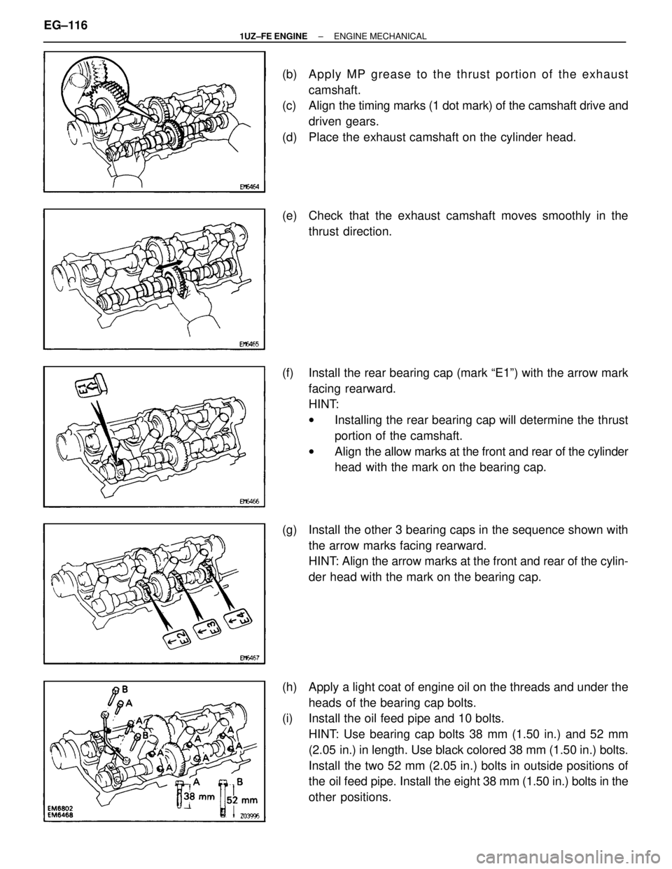
(b) Apply MP grease to the thrust portion of the exhaustcamshaft.
(c) Align the timing marks (1 dot mark) of the camshaft drive and
driven gears.
(d) Place the exhaust camshaft on the cylinder head.
(e) Check that the exhaust camshaft moves smoothly in the thrust direction.
(f) Install the rear bearing cap (mark ªE1º) with the arrow mark facing rearward.
HINT:
wInstalling the rear bearing cap will determine the thrust
portion of the camshaft.
w Align the allow marks at the front and rear of the cylinder
head with the mark on the bearing cap.
(g) Install the other 3 bearing caps in the sequence shown with the arrow marks facing rearward.
HINT: Align the arrow marks at the front and rear of the cylin-
der head with the mark on the bearing cap.
(h) Apply a light coat of engine oil on the threads and under the heads of the bearing cap bolts.
(i) Install the oil feed pipe and 10 bolts.
HINT: Use bearing cap bolts 38 mm (1.50 in.) and 52 mm
(2.05 in.) in length. Use black colored 38 mm (1.50 in.) bolts.
Install the two 52 mm (2.05 in.) bolts in outside positions of
the oil feed pipe. Install the eight 38 mm (1.50 in.) bolts in the
other positions.
EG±116
±
1UZ±FE ENGINE ENGINE MECHANICAL
WhereEverybodyKnowsYourName
Page 1495 of 4087

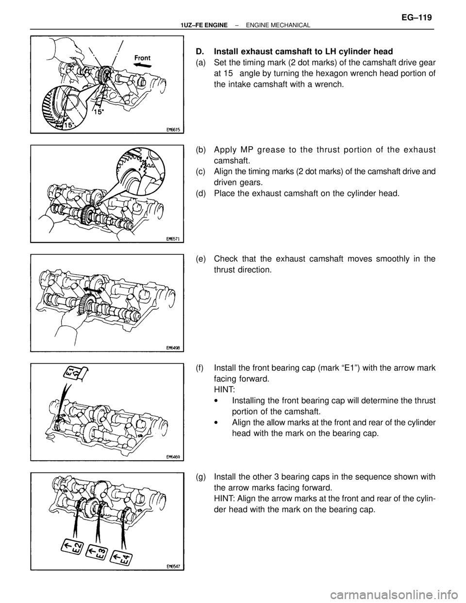
D. Install exhaust camshaft to LH cylinder head
(a) Set the timing mark (2 dot marks) of the camshaft drive gearat 15 � angle by turning the hexagon wrench head portion of
the intake camshaft with a wrench.
(b) A p p ly MP gre a se to th e th ru st po rtio n of th e ex haust
camshaft.
(c) Align the timing marks (2 dot marks) of the camshaft drive and
driven gears.
(d) Place the exhaust camshaft on the cylinder head.
(e) Check that the exhaust camshaft moves smoothly in the thrust direction.
(f) Install the front bearing cap (mark ªE1º) with the arrow mark facing forward.
HINT:
wInstalling the front bearing cap will determine the thrust
portion of the camshaft.
w Align the allow marks at the front and rear of the cylinder
head with the mark on the bearing cap.
(g) Install the other 3 bearing caps in the sequence shown with the arrow marks facing forward.
HINT: Align the arrow marks at the front and rear of the cylin-
der head with the mark on the bearing cap.
±
1UZ±FE ENGINE ENGINE MECHANICALEG±119
WhereEverybodyKnowsYourName
Page 1496 of 4087

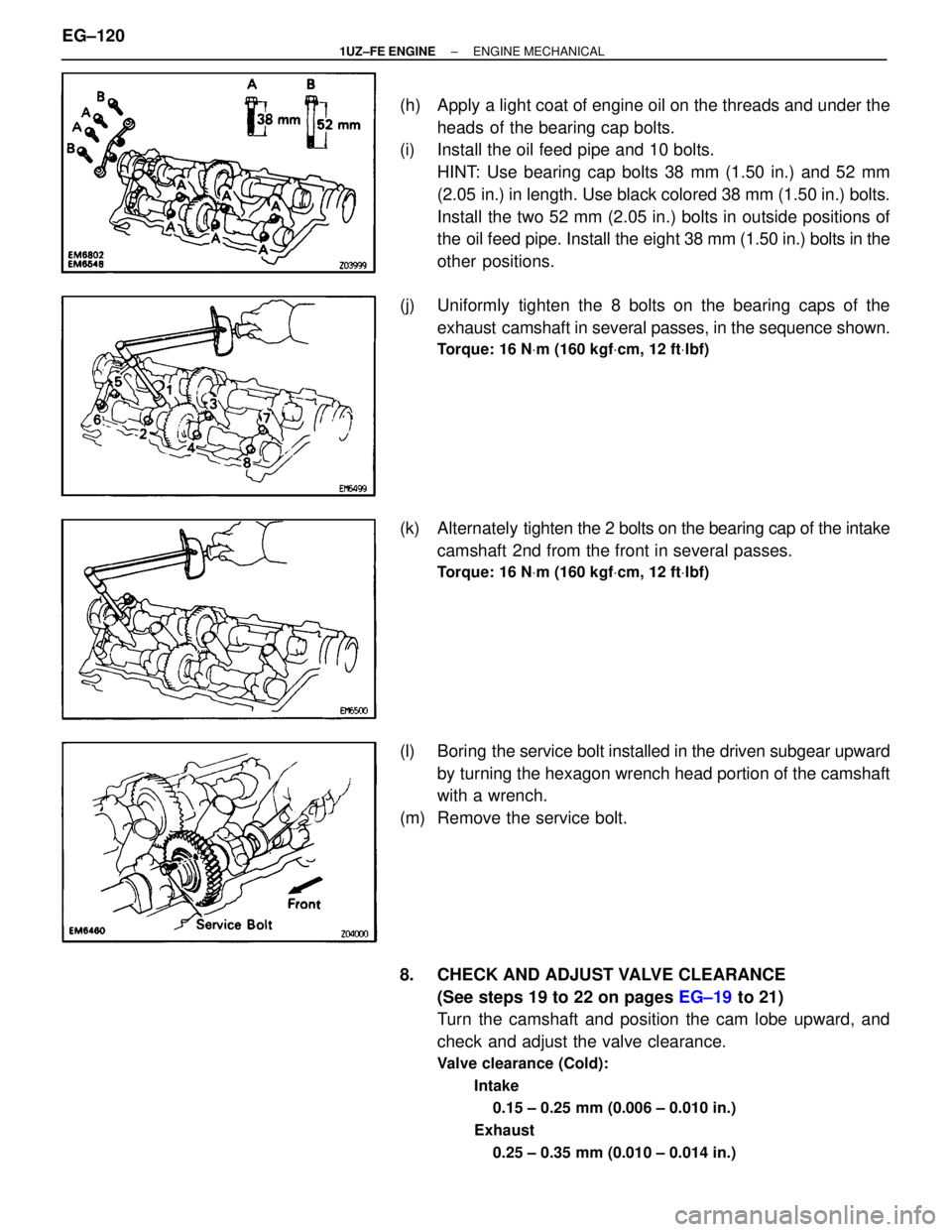
(h) Apply a light coat of engine oil on the threads and under theheads of the bearing cap bolts.
(i) Install the oil feed pipe and 10 bolts.
HINT: Use bearing cap bolts 38 mm (1.50 in.) and 52 mm
(2.05 in.) in length. Use black colored 38 mm (1.50 in.) bolts.
Install the two 52 mm (2.05 in.) bolts in outside positions of
the oil feed pipe. Install the eight 38 mm (1.50 in.) bolts in the
other positions.
(j) Uniformly tighten the 8 bolts on the bearing caps of the exhaust camshaft in several passes, in the sequence shown.
Torque: 16 N Vm (160 kgf Vcm, 12 ft Vlbf)
(k) Alternately ti ghten the 2 bolts on the bearing cap of the intake
camshaft 2nd from the front in several passes.
Torque: 16 N Vm (160 kgf Vcm, 12 ft Vlbf)
(l) Boring the service bolt installed in the driven subgear upward
by turning the hexagon wrench head portion of the camshaft
with a wrench.
(m) Remove the service bolt.
8. CHECK AND ADJUST VALVE CLEARANCE (See steps 19 to 22 on pages EG±19 to 21)
Turn the camshaft and position the cam lobe upward, and
check and adjust the valve clearance.
Valve clearance (Cold):
Intake0.15 ± 0.25 mm (0.006 ± 0.010 in.)
Exhaust 0.25 ± 0.35 mm (0.010 ± 0.014 in.)
EG±120±
1UZ±FE ENGINE ENGINE MECHANICAL
WhereEverybodyKnowsYourName
Page 1501 of 4087
(e) Place 8 new insulators and the 4 spacers in position on theintake manifold.
(f) Place the 8 injectors and 2 delivery pipes assembly in position on the intake manifold.
(g) Temporarily install the connector bracket and 4 nuts.
(h) Check that the injectors rotate smoothly.
HINT: If injectors do not rotate smoothly, the probable cause
is incorrect installation of O±rings. Replace the O±rings.
(i) Position the injector connector upward.
(j) Tighten the 4 nuts holding the delivery pipes to the intake manifold.
Torque: 18 N Vm (185 kgf Vcm, 13 ft Vlbf)
21. INSTALL FUEL RETURN PIPE
(a) Temporarily install the fuel return pipe with the bolt, 2 new
gaskets and union bolt.
(b) Tighten the union bolt holding the return pipe to the fuel pressure regulator.
Torque: 35 N Vm (360 kgf Vcm, 26 ft Vlbf)
(c) Tighten the bolt holding the return pipe to the LH cylinder
head.
±
1UZ±FE ENGINE ENGINE MECHANICALEG±125
WhereEverybodyKnowsYourName
Page 1512 of 4087
45. INSTALL LH CAMSHAFT TIMING PULLEY
(a) Align the camshaft knock pin with the knock pin groove of the
timing pulley, and slide on the timing pulley.
(b) Slide the timing pulley on the camshaft, facing the ªLº mark forward.
(c) Using SST, install the pulley bolt. SST 09278±54012
Torque: 108 N Vm (1,100 kgf Vcm, 80 ft Vlbf)
46. C O N N E C T T I M I N G B E LT TO C A M S H A F T T I M I N G
PULLEYS
(See steps 10 to 40 on pages EG±61 to 72)
47. CONNECT NEGATIVE TERMINAL CABLE TO BATTERY
48. FILL WITH ENGINE COOLANT
49. START ENGINE AND CHECK FOR LEAKS
50. CHECK TRANSMISSION FLUID LEVEL
51. PERFORM ENGINE ADJUSTMENT (See Tune±Up on pages EG±9 to 34)
52. PERFORM ROAD TEST Check for abnormal noise, shock, slipage, correct shift points
and smooth operation.
53. INSTALL ENGINE UNDER COVER
EG±136
±
1UZ±FE ENGINE ENGINE MECHANICAL
WhereEverybodyKnowsYourName
Page 1532 of 4087

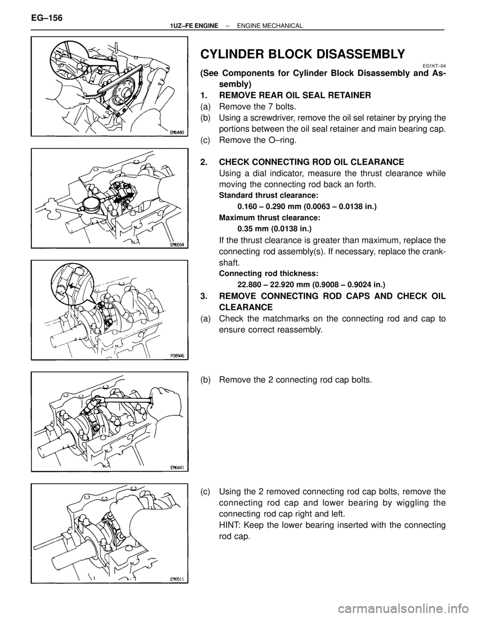
CYLINDER BLOCK DISASSEMBLY
EG1KT±04
(See Components for Cylinder Block Disassembly and As-sembly)
1. REMOVE REAR OIL SEAL RETAINER
(a) Remove the 7 bolts.
(b) Using a screwdriver, remove the oil sel retainer by prying the portions between the oil seal retainer and main bearing cap.
(c) Remove the O±ring.
2. CHECK CONNECTING ROD OIL CLEARANCE Using a dial indicator, measure the thrust clearance while
moving the connecting rod back an forth.
Standard thrust clearance:
0.160 ± 0.290 mm (0.0063 ± 0.0138 in.)
Maximum thrust clearance: 0.35 mm (0.0138 in.)
If the thrust clearance is greater than maximum, replace the
connecting rod assembly(s). If necessary, replace the crank-
shaft.
Connecting rod thickness:
22.880 ± 22.920 mm (0.9008 ± 0.9024 in.)
3. REMOVE CONNECTING ROD CAPS AND CHECK OILCLEARANCE
(a) Check the matchmarks on the connecting rod and cap to ensure correct reassembly.
(b) Remove the 2 connecting rod cap bolts.
(c) Using the 2 removed connecting rod cap bolts, remove the connecting rod cap and lower bearing by wiggling the
connecting rod cap right and left.
HINT: Keep the lower bearing inserted with the connecting
rod cap.
EG±156
±
1UZ±FE ENGINE ENGINE MECHANICAL
WhereEverybodyKnowsYourName