Page 1439 of 4087

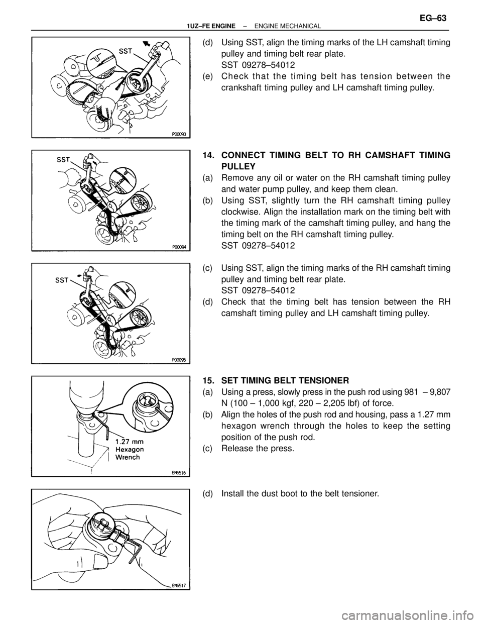
(d) Using SST, align the timing marks of the LH camshaft timingpulley and timing belt rear plate.
SST 09278±54012
(e) C h e c k t h a t t h e t i m i n g b e l t h a s t e n s i o n b e t w e e n t h e
crankshaft timing pulley and LH camshaft timing pulley.
14. CONNECT TIMING BELT TO RH CAMSHAFT TIMING PULLEY
(a) Remove any oil or water on the RH camshaft timing pulley
and water pump pulley, and keep them clean.
(b) Using SST, slightly turn the RH camshaft timing pulley clockwise. Align the installation mark on the timing belt with
the timing mark of the camshaft timing pulley, and hang the
timing belt on the RH camshaft timing pulley.
SST 09278±54012
(c) Using SST, align the timing marks of the RH camshaft timing pulley and timing belt rear plate.
SST 09278±54012
(d) Check that the timing belt has tension between the RH camshaft timing pulley and LH camshaft timing pulley.
15. SET TIMING BELT TENSIONER
(a) Using a press, slowly press in the push rod using 981 ± 9,807
N (100 ± 1,000 kgf, 220 ± 2,205 lbf) of force.
(b) Align the holes of the push rod and housing, pass a 1.27 mm hexagon wrench through the holes to keep the setting
position of the push rod.
(c) Release the press.
(d) Install the dust boot to the belt tensioner.
±
1UZ±FE ENGINE ENGINE MECHANICALEG±63
WhereEverybodyKnowsYourName
Page 1440 of 4087
16. INSTALL TIMING BELT TENSIONER
(a) Temporarily install the belt tensioner with the 2 bolts.
(b) Alternately tighten the 2 bolts.
Torque: 26 NVm (270 kgf Vcm, 20 ft Vlbf)
(c) Using pliers, remove the 1.27 mm hexagon wrench from the
belt tensioner.
17. CHECK VALVE TIMING
(a) Slowly turn the crankshaft pulley 2 revolutions from TDC to TDC.
NOTICE: Always turn the crankshaft pulley clockwise.
(b) Check that each pulley aligns with the timing marks as shown
in the illustration.
If the timing marks do not align, remove the timing belt and
reinstall it.
18. INSTALL SPARK PLUGS Using a 16 mm plug wrench, install the 8 spark plugs.
Torque: 18 N Vm (180 kgf Vcm, 13 ft Vlbf)
EG±64±
1UZ±FE ENGINE ENGINE MECHANICAL
WhereEverybodyKnowsYourName
Page 1448 of 4087
39. INSTALL RADIATOR RESERVOIR TANK
(a) Install the reservoir tank to the reservoir tank bracket.
(b) Install the reservoir tank with the bracket and 3 bolts.
Torque: 4.9 NVm (50 kgf Vcm, 43 in. Vlbf)
(c) Connect the following hoses:
(1) Reservoir hose to water inlet housing
(2) Reservoir hose to radiator
(d) Connect the coolant level sensor connector.
40. INSTALL DRIVE BELT Install the drive belt by turning the drive belt tensioner coun-
terclockwise.
HINT: The pulley bolt for the dive belt tensioner has a left
hand thread.
41. INSTALL BATTERY
42. FILL WITH ENGINE COOLANT
43. START ENGINE AND CHECK FOR LEAKS
44. CHECK TRANSMISSION FLUID LEVEL
45. INSTALL ENGINE UNDER COVER
EG±72
±
1UZ±FE ENGINE ENGINE MECHANICAL
WhereEverybodyKnowsYourName
Page 1472 of 4087
D. Clean cylinder headUsing a soft brush and solvent, thoroughly clean the cylinder
head.
3. INSPECT CYLINDER HEAD
A. Inspect for flatness Using a precision straight edge and feeler gauge, measure
the surface contacting the cylinder block and the manifolds
for warpage.
Maximum warpage:
0.10 mm (0.0039 in.)
If warpage is greater than maximum, replace the cylinder
head.
B. Inspect for cracks Using a dye penetrant, check the combustion chamber, in-
take ports, exhaust ports and cylinder block surface for
cracks.
If cracked, replace the cylinder head.
4. CLEAN VALVES
(a) Using a gasket scraper, chip off any carbon from the valve head.
(b) Using a wire brush, thoroughly clean the valve.
EG±96
±
1UZ±FE ENGINE ENGINE MECHANICAL
WhereEverybodyKnowsYourName
Page 1475 of 4087
(f) Gradually heat the cylinder head to 80 ± 100�C (176 ±
212 �F).
(g) Using SST and a hammer, tap in a new guide bushing until the snap ring makes contact with the cylinder head.
SST 09201±70010
(h) Using a sharp 6 mm reamer, ream the guide bushing to obtain
the standard specified clearance (See step 5 above)
between the guide bushing and valve stem.
7. INSPECT AND GRIND VALVES
(a) Grind the valve enough to remove pits and carbon.
(b) Check that the valve is ground to the correct valve face angle.
Valve face angle:
44.55
(c) Check the valve head margin thickness.
Standard margin thickness:
1.0 mm (0.039 in.)
Minimum margin thickness: 0.5 mm (0.020 in.)
If the margin thickness is less than minimum, replace the
valve.
±
1UZ±FE ENGINE ENGINE MECHANICALEG±99
WhereEverybodyKnowsYourName
Page 1476 of 4087

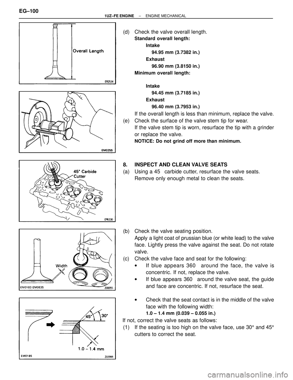
(d) Check the valve overall length.
Standard overall length:Intake94.95 mm (3.7382 in.)
Exhaust 96.90 mm (3.8150 in.)
Minimum overall length:
Intake94.45 mm (3.7185 in.)
Exhaust 96.40 mm (3.7953 in.)
If the overall length is less than minimum, replace the valve.
(e) Check the surface of the valve stem tip for wear. If the valve stem tip is worn, resurface the tip with a grinder
or replace the valve.
NOTICE: Do not grind off more than minimum.
8. INSPECT AND CLEAN VALVE SEATS
(a) Using a 45 � carbide cutter, resurface the valve seats.
Remove only enough metal to clean the seats.
(b) Check the valve seating position. Apply a light coat of prussian blue (or white lead) to the valve
face. Lightly press the valve against the seat. Do not rotate
valve.
(c) Check the valve face and seat for the following: wIf blue appears 360 � around the face, the valve is
concentric. If not, replace the valve.
w If blue appears 360 � around the valve seat, the guide
and face are concentric. If not, resurface the seat.
w Check that the seat contact is in the middle of the valve
face with the following width:
1.0 ± 1.4 mm (0.039 ± 0.055 in.)
If not, correct the valve seats as follows:
(1) If the seating is too high on the valve face, use 30 5 and 45 5
cutters to correct the seat.
EG±100
±
1UZ±FE ENGINE ENGINE MECHANICAL
WhereEverybodyKnowsYourName
Page 1478 of 4087

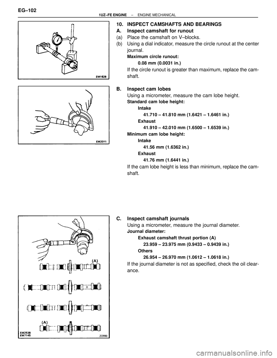
10. INSPECT CAMSHAFTS AND BEARINGS
A. Inspect camshaft for runout
(a) Place the camshaft on V±blocks.
(b) Using a dial indicator, measure the circle runout at the centerjournal.
Maximum circle runout:
0.08 mm (0.0031 in.)
If the circle runout is greater than maximum, replace the cam-
shaft.
B. Inspect cam lobes Using a micrometer, measure the cam lobe height.
Standard cam lobe height:
Intake41.710 ± 41.810 mm (1.6421 ± 1.6461 in.)
Exhaust 41.910 ± 42.010 mm (1.6500 ± 1.6539 in.)
Minimum cam lobe height: Intake41.56 mm (1.6362 in.)
Exhaust
41.76 mm (1.6441 in.)
If the cam lobe height is less than minimum, replace the cam-
shaft.
C. Inspect camshaft journals Using a micrometer, measure the journal diameter.
Journal diameter:
Exhaust camshaft thrust portion (A)23.959 ± 23.975 mm (0.9433 ± 0.9439 in.)
Others 26.954 ± 26.970 mm (1.0612 ± 1.0618 in.)
If the journal diameter is not as specified, check the oil clear-
ance.
EG±102
±
1UZ±FE ENGINE ENGINE MECHANICAL
WhereEverybodyKnowsYourName
Page 1479 of 4087
D. Inspect camshaft bearingsCheck that bearings for flaking and scoring.
If the bearings are damaged, replace the bearing caps and
cylinder head a set.
E. Inspect camshaft gear spring Using a vernier caliper measure the free distance between
the spring ends.
Free distance:
18.2 ± 18.8 mm (0.712 ± 0.740 in.)
If the free distance is not as specified, replace the gear
spring.
F. Inspect camshaft journal oil clearance
(a) Clean the bearing caps and camshaft journals.
(b) Place the camshafts on the cylinder head.
(c) Lay a strip of Plasti gage across each of the camshaft
journals.
(d) Install the bearing caps. (See step 7 on pages EG±114 to 120)
Torque: 16 N Vm (160 kgf Vcm, 12 ft Vlbf)
NOTICE: Do not turn the camshaft.
(e) Remove the bearing caps.
±
1UZ±FE ENGINE ENGINE MECHANICALEG±103
WhereEverybodyKnowsYourName