Page 1608 of 4087
3. INSPECT CYLINDER FOR VERTICAL SCRATCHESVisually check the cylinder for vertical scratches.
If deep scratches are present, replace the cylinder block.
4. INSPECT CYLINDER BORE DIAMETER HINT: There are three sizes of the standard cylinder bore di-
ameter, marked º1º, º2º and º3º accordingly. The marked is
stamped on the top of the cylinder block.
Using a cylinder gauge, measure the cylinder bore diameter
at positions A, B and C in the thrust and axial directions.
Standard diameter:
Mark º1º 87.500±87.510 mm (3.4449±3.4453 in.)
Mark º2º 87.510±87.520 mm (3.4453±3.4457 in.)
Mark º3º 87.520±87.530 mm (3.4457±3.4461 in.)
Maximum diameter: 87.73 mm (3.4539 in.)
If the diameter is greater than maximum, replace the cylinder
block.
5. REMOVE CYLINDER RIDGE If the wear is less than 0.2 mm (0.008 in.), using a ridge ream-
er, grind the top of the cylinder.
±
ENGINE MECHANICAL Cylinder BlockEM±143
WhereEverybodyKnowsYourName
Page 1609 of 4087

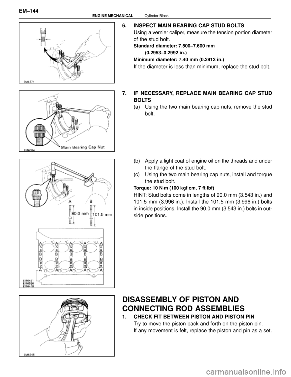
6. INSPECT MAIN BEARING CAP STUD BOLTSUsing a vernier caliper, measure the tension portion diameter
of the stud bolt.
Standard diameter: 7.500±7.600 mm
(0.2953±0.2992 in.)
Minimum diameter: 7.40 mm (0.2913 in.)
If the diameter is less than minimum, replace the stud bolt.
7. IF NECESSARY, REPLACE MAIN BEARING CAP STUD BOLTS
(a) Using the two main bearing cap nuts, remove the studbolt.
(b) Apply a light coat of engine oil on the threads and under
the flange of the stud bolt.
(c) Using the two main bearing cap nuts, install and torque
the stud bolt.
Torque: 10 N Vm (100 kgf Vcm, 7 ft Vlbf)
HINT: Stud bolts come in lengths of 90.0 mm (3.543 in.) and
101.5 mm (3.996 in.). Install the 101.5 mm (3.996 in.) bolts
in inside positions. Install the 90.0 mm (3.543 in.) bolts in out-
side positions.
DISASSEMBLY OF PISTON AND
CONNECTING ROD ASSEMBLIES
1. CHECK FIT BETWEEN PISTON AND PISTON PIN
Try to move the piston back and forth on the piston pin.
If any movement is felt, replace the piston and pin as a set.
EM±144
±
ENGINE MECHANICAL Cylinder Block
WhereEverybodyKnowsYourName
Page 1614 of 4087

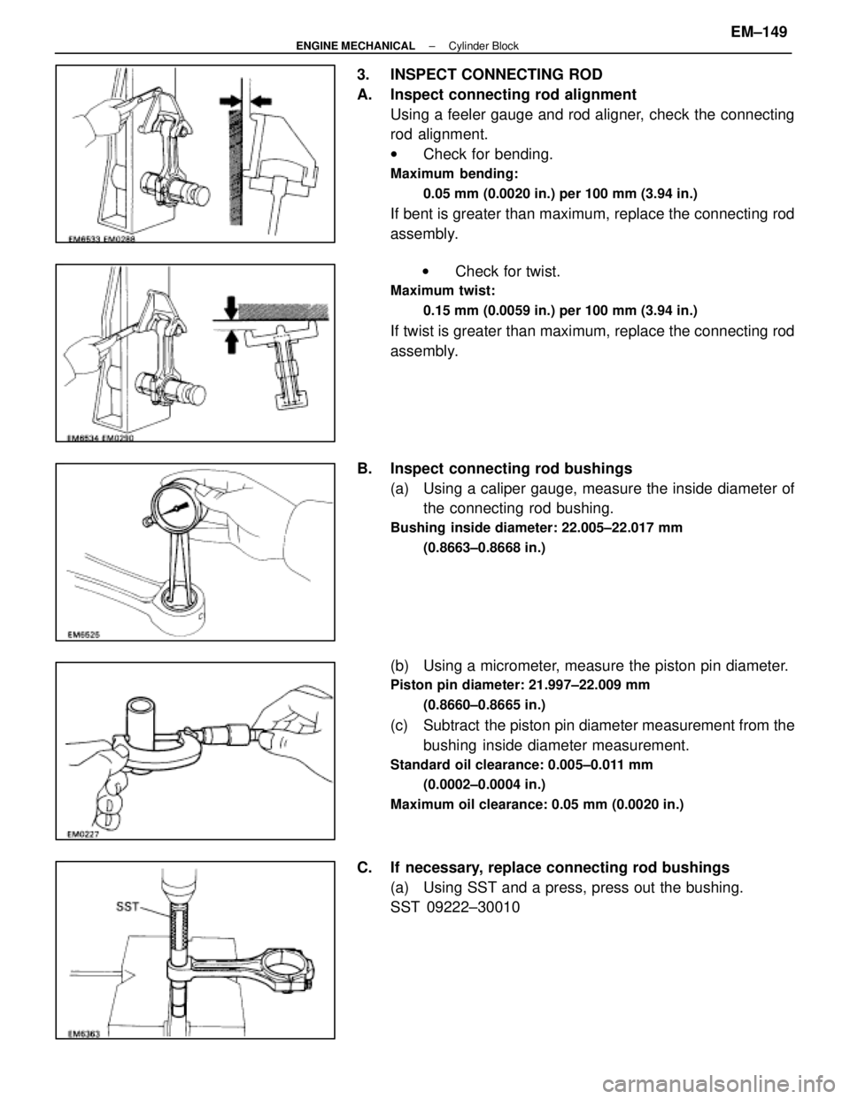
3. INSPECT CONNECTING ROD
A. Inspect connecting rod alignmentUsing a feeler gauge and rod aligner, check the connecting
rod alignment.
wCheck for bending.
Maximum bending:
0.05 mm (0.0020 in.) per 100 mm (3.94 in.)
If bent is greater than maximum, replace the connecting rod
assembly.
w Check for twist.
Maximum twist:
0.15 mm (0.0059 in.) per 100 mm (3.94 in.)
If twist is greater than maximum, replace the connecting rod
assembly.
B. Inspect connecting rod bushings (a) Using a caliper gauge, measure the inside diameter ofthe connecting rod bushing.
Bushing inside diameter: 22.005±22.017 mm
(0.8663±0.8668 in.)
(b) Using a micrometer, measure the piston pin diameter.
Piston pin diameter: 21.997±22.009 mm(0.8660±0.8665 in.)
(c) Subtract the piston pin diameter measurement from thebushing inside diameter measurement.
Standard oil clearance: 0.005±0.011 mm
(0.0002±0.0004 in.)
Maximum oil clearance: 0.05 mm (0.0020 in.)
C. If necessary, replace connecting rod bushings (a) Using SST and a press, press out the bushing.
SST 09222±30010
±
ENGINE MECHANICAL Cylinder BlockEM±149
WhereEverybodyKnowsYourName
Page 1615 of 4087
(b) Align the oil holes of the connecting rod and a newbushing.
(c) Using SST and a press, press in the bushing.
SST 09222±30010
(d) Using a pin hole grinder, hole the bushing to obtain the standard specified clearance (see step B above)
between the bushing and piston pin.
(e) Check the piston pin fit at normal room temperature.
Coat the piston pin with engine oil, and push it into the con-
necting rod with your thumb.
D. Inspect connecting rod bolts Using a vernier caliper, measure the tension portion diameter
of the bolt.
Standard diameter: 7.200±7.300 mm
(0.2835±0.2874 in.)
Minimum diameter: 7.00 mm (0.2756 in.)
If the outside diameter is less than minimum, replace the bolt.
EM±150
±
ENGINE MECHANICAL Cylinder Block
WhereEverybodyKnowsYourName
Page 1616 of 4087
INSPECTION OF CRANKSHAFT
1. INSPECT CRANKSHAFT FOR RUNOUT(a) Place the crankshaft on V±blocks.
(b) Using a dial indicator, measure the circle runout at thecenter journal.
Maximum circle runout: 0.08 mm (0.0031 in.)
If the circle runout is greater than maximum, replace the
crankshaft.
2. INSPECT MAIN JOURNALS AND CRANK PINS (a) Using a micr ometer, measure the diameter of each main
journal and crank pin.
Main journal diameter: 66.988±67.000 mm
(2.6373±2.6378 in.)
Crank pin diameter: 51.982±52.000 mm (2.0465±2.0472 in.)
If the diameter is not as specified, check the oil clearance
(See page EM±136 or 139).
(b) Check each main journal and crank pin for taper and out±of±round as shown.
Maximum taper and out±of±round: 0.02 mm
(0.0008 in.)
If the taper or out±of±round is greater than maximum, re-
place the crankshaft.
±
ENGINE MECHANICAL Cylinder BlockEM±151
WhereEverybodyKnowsYourName
Page 1623 of 4087
(c) Mark the front of the main bearing cap nut with paint.
(d) R e t i g h t e n t h e m a i n b e a r i n g c a p n u t s 9 0 5 i n t h enumerical order shown.
(e) Check that the painted mark is now at a 905 angle to the
front.
(f) Check that the crankshaft turns smoothly.
(g) Check the crankshaft thrust clearance. (See step 5 on page EM±138)
C. Install main bearing cap bolts (a) Install a new seal washer to the main bearing cap bolt.
(b) Install the ten main bearing cap bolts.
Torque: 49 N Vm (500 kgf Vcm, 36 ft Vlbf)
5. INSTALL PISTON AND CONNECTING ROD ASSEMBLIES
Using a piston ring compressor, push the correctly numbered
piston and connecting rod assemblies into each cylinder with
the front mark of the piston facing forward.
NOTICE: The shape of the piston varies for the RH and LH
banks. The RH piston is marked with ºRº, the LH piston
with ºLº.
EM±158
±
ENGINE MECHANICAL Cylinder Block
WhereEverybodyKnowsYourName
Page 1624 of 4087

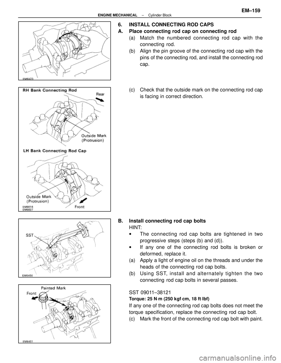
6. INSTALL CONNECTING ROD CAPS
A. Place connecting rod cap on connecting rod(a) Match the numbered c onnecting rod cap with the
connecting rod.
(b) Align the pin groove of the connecting rod cap with the pins of the connecting rod, and install the connecting rod
cap.
(c) Check that the outside mark on the connecting rod cap is facing in correct direction.
B. Install connecting rod cap bolts HINT:
wThe connecting rod cap bolts are tightened in two
progressive steps (steps (b) and (d)).
w If any one of the connecting rod bolts is broken or
deformed, replace it.
(a) Apply a light of engine oil on the threads and under the
heads of the connecting rod cap bolts.
(b) Usin g SS T, in sta ll an d alte rn a te ly tig h te n th e two connecting rod cap bolts in several passes.
SST 09011±38121
Torque: 25 N Vm (250 kgf Vcm, 18 ft Vlbf)
If any one of the connecting rod cap bolts does not meet the
torque specification, replace the connecting rod cap bolt.
(c) Mark the front of the connecting rod cap bolt with paint.
±
ENGINE MECHANICAL Cylinder BlockEM±159
WhereEverybodyKnowsYourName
Page 1625 of 4087

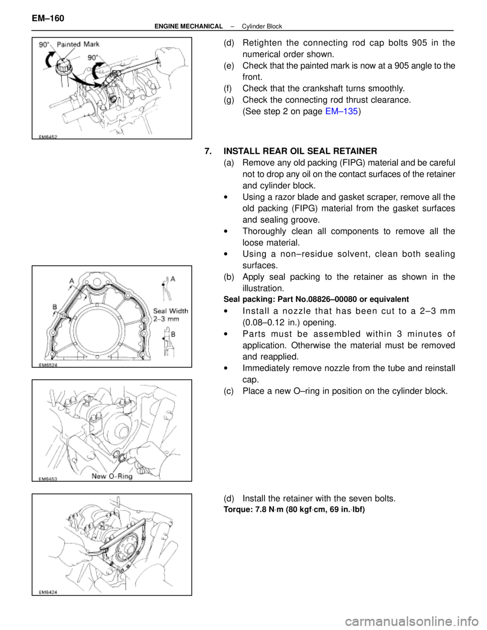
(d) Retighten the connecting rod cap bolts 905 in thenumerical order shown.
(e) Check that the painted mark is now at a 905 angle to the
front.
(f) Check that the crankshaft turns smoothly.
(g) Check the connecting rod thrust clearance. (See step 2 on page EM±135)
7. INSTALL REAR OIL SEAL RETAINER (a) Remove any old packing (FIPG) material and be carefulnot to drop any oil on the contact surfaces of the retainer
and cylinder block.
w Using a razor blade and gasket scraper, remove all the
old packing (FIPG) material from the gasket surfaces
and sealing groove.
w Thoroughly clean all components to remove all the
loose material.
w Using a non±residue solvent, clean both sealing
surfaces.
(b) Apply seal packing to the retainer as shown in the illustration.
Seal packing: Part No.08826±00080 or equivalent
wInstall a nozzle that has been cut to a 2±3 mm
(0.08±0.12 in.) opening.
w Parts must be assembled within 3 minutes of
application. Otherwise the material must be removed
and reapplied.
w Immediately remove nozzle from the tube and reinstall
cap.
(c) Place a new O±ring in position on the cylinder block.
(d) Install the retainer with the seven bolts.
Torque: 7.8 N Vm (80 kgf Vcm, 69 in. Vlbf)
EM±160±
ENGINE MECHANICAL Cylinder Block
WhereEverybodyKnowsYourName