Page 1557 of 4087
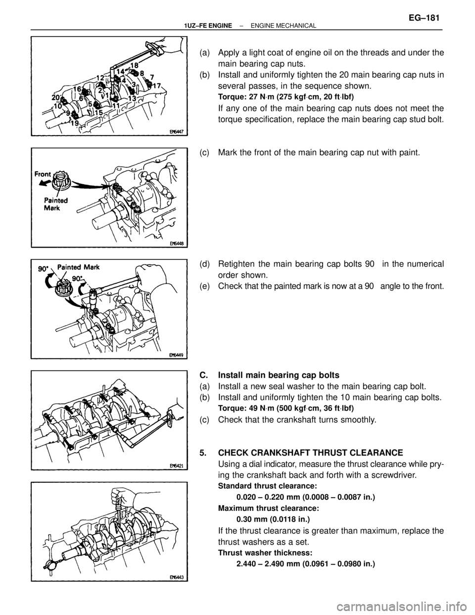
(a) Apply a light coat of engine oil on the threads and under themain bearing cap nuts.
(b) Install and uniformly tighten the 20 main bearing cap nuts in
several passes, in the sequence shown.
Torque: 27 N Vm (275 kgf Vcm, 20 ft Vlbf)
If any one of the main bearing cap nuts does not meet the
torque specification, replace the main bearing cap stud bolt.
(c) Mark the front of the main bearing cap nut with paint.
(d) Retighten the main bearing cap bolts 90 � in the numerical
order shown.
(e) Check that the painted mark is now at a 90 � angle to the front.
C. Install main bearing cap bolts
(a) Install a new seal washer to the main bearing cap bolt.
(b) Install and uniformly tighten the 10 main bearing cap bolts.
Torque: 49 N Vm (500 kgf Vcm, 36 ft Vlbf)
(c) Check that the crankshaft turns smoothly.
5. CHECK CRANKSHAFT THRUST CLEARANCE
Using a dial indi cator, measure the thrust clearance while pry-
ing the crankshaft back and forth with a screwdriver.
Standard thrust clearance:
0.020 ± 0.220 mm (0.0008 ± 0.0087 in.)
Maximum thrust clearance: 0.30 mm (0.0118 in.)
If the thrust clearance is greater than maximum, replace the
thrust washers as a set.
Thrust washer thickness:2.440 ± 2.490 mm (0.0961 ± 0.0980 in.)
±
1UZ±FE ENGINE ENGINE MECHANICALEG±181
WhereEverybodyKnowsYourName
Page 1558 of 4087
6. INSTALL PISTON AND CONNECTING ROD ASSEMBLESUsing a piston ring compressor, push the correctly numbered
piston and connecting rod assemblies into each cylinder with
the front mark of the piston facing forward.
NOTICE: The shape of the piston varies for the RH and LH
banks. The RH piston is marked with ªRº, the LH piston
with ªLº.
7. INSTALL CONNECTING ROD CAPS
A. Place connecting rod cap on connecting rod
(a) Match the numbered connecting rod cap with the connecting rod.
(b) Align the pin groove of the connecting rod cap with the pins of the connecting rod, and install the connecting rod.
(c) Check that the outside mark of the connecting rod cap is facing in correct direction.
EG±182
±
1UZ±FE ENGINE ENGINE MECHANICAL
WhereEverybodyKnowsYourName
Page 1559 of 4087
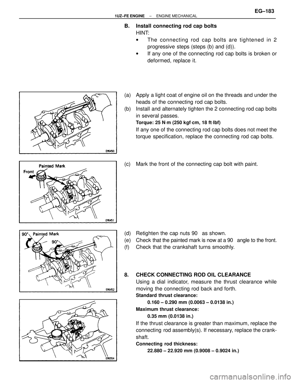
B. Install connecting rod cap boltsHINT:
wThe connecting rod cap bolts are tightened in 2
progressive steps (steps (b) and (d)).
w If any one of the connecting rod cap bolts is broken or
deformed, replace it.
(a) Apply a light coat of engine oil on the threads and under the heads of the connecting rod cap bolts.
(b) Install and alternately tighten the 2 connecting rod cap bolts
in several passes.
Torque: 25 N Vm (250 kgf Vcm, 18 ft Vlbf)
If any one of the connecting rod cap bolts does not meet the
torque specification, replace the connecting rod cap bolts.
(c) Mark the front of the connecting cap bolt with paint.
(d) Retighten the cap nuts 90 � as shown.
(e) Check that the painted mark is now at a 90 � angle to the front.
(f) Check that the crankshaft turns smoothly.
8. CHECK CONNECTING ROD OIL CLEARANCE
Using a dial indicator, measure the thrust clearance while
moving the connecting rod back and forth.
Standard thrust clearance:
0.160 ± 0.290 mm (0.0063 ± 0.0138 in.)
Maximum thrust clearance: 0.35 mm (0.0138 in.)
If the thrust clearance is greater than maximum, replace the
connecting rod assembly(s). If necessary, replace the crank-
shaft.
Connecting rod thickness:22.880 ± 22.920 mm (0.9008 ± 0.9024 in.)
±
1UZ±FE ENGINE ENGINE MECHANICALEG±183
WhereEverybodyKnowsYourName
Page 1570 of 4087
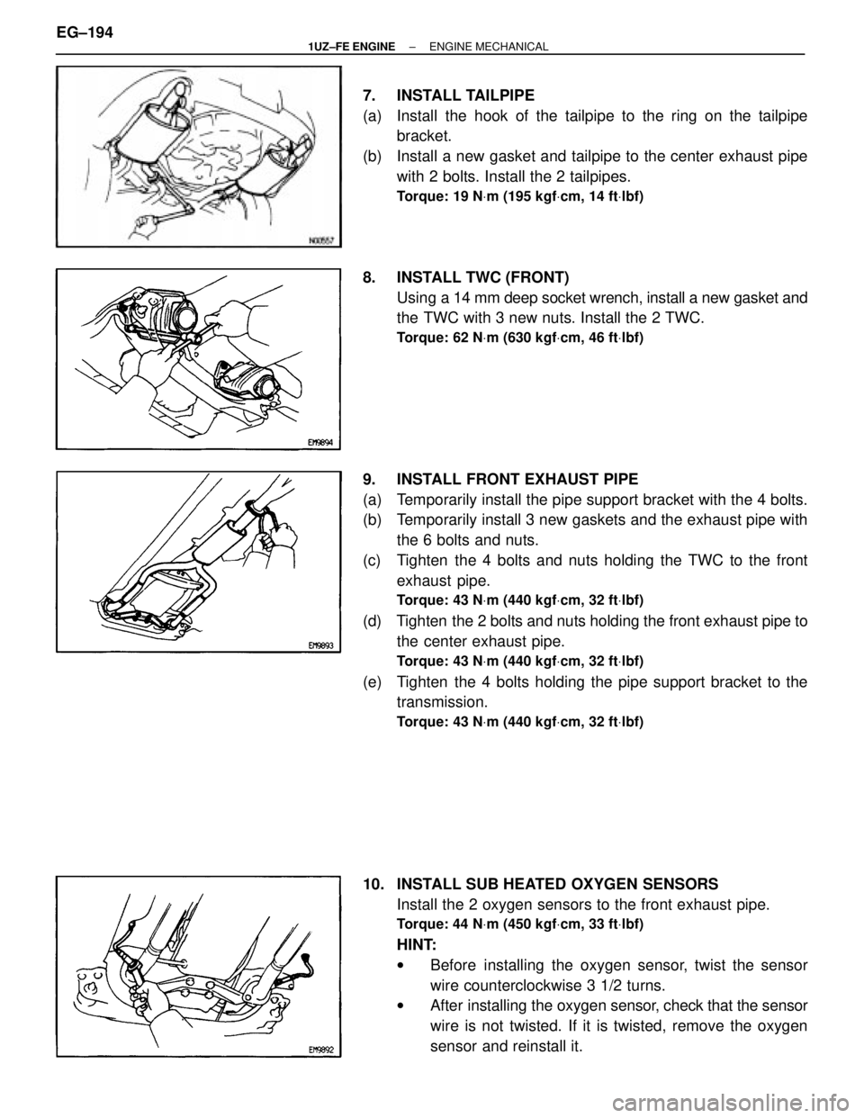
7. INSTALL TAILPIPE
(a) Install the hook of the tailpipe to the ring on the tailpipebracket.
(b) Install a new gasket and tailpipe to the center exhaust pipe with 2 bolts. Install the 2 tailpipes.
Torque: 19 N Vm (195 kgf Vcm, 14 ft Vlbf)
8. INSTALL TWC (FRONT)
Using a 14 mm deep socket wrench, install a new gasket and
the TWC with 3 new nuts. Install the 2 TWC.
Torque: 62 N Vm (630 kgf Vcm, 46 ft Vlbf)
9. INSTALL FRONT EXHAUST PIPE
(a) Temporarily install the pipe support bracket with the 4 bolts.
(b) Temporarily install 3 new gaskets and the exhaust pipe with
the 6 bolts and nuts.
(c) Tighten the 4 bolts and nuts holding the TWC to the front exhaust pipe.
Torque: 43 N Vm (440 kgf Vcm, 32 ft Vlbf)
(d) Tighten the 2 bolts and nuts holding the front exhaust pipe to
the center exhaust pipe.
Torque: 43 N Vm (440 kgf Vcm, 32 ft Vlbf)
(e) Tighten the 4 bolts holding the pipe support bracket to the
transmission.
Torque: 43 N Vm (440 kgf Vcm, 32 ft Vlbf)
10. INSTALL SUB HEATED OXYGEN SENSORS
Install the 2 oxygen sensors to the front exhaust pipe.
Torque: 44 N Vm (450 kgf Vcm, 33 ft Vlbf)
HINT:
w Before installing the oxygen sensor, twist the sensor
wire counterclockwise 3 1/2 turns.
w After installing the oxygen sensor, check that the sensor
wire is not twisted. If it is twisted, remove the oxygen
sensor and reinstall it.
EG±194
±
1UZ±FE ENGINE ENGINE MECHANICAL
WhereEverybodyKnowsYourName
Page 1579 of 4087
34. FILL WITH ENGINE COOLANT
35. FILL WITH ENGINE OIL
36. START ENGINE AND CHECK FOR LEAKS
37. CHECK TRANSMISSION FLUID LEVEL
38. PERFORM ENGINE ADJUSTMENT(See Tune±Up on pages EG±9 to 34)
39. INSTALL ENGINE UNDER COVER
40. INSTALL HOOD
41. PERFORM ROAD TEST Check for abnormal noise, shock slippage, correct shift
points and smooth operation.
42. RECHECK ENGINE COOLANT AND OIL LEVELS
±
1UZ±FE ENGINE ENGINE MECHANICALEG±203
WhereEverybodyKnowsYourName
Page 1600 of 4087
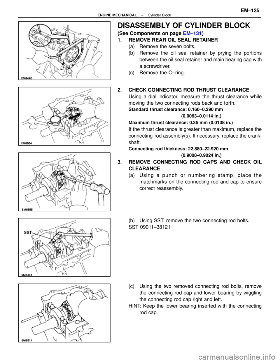
DISASSEMBLY OF CYLINDER BLOCK
(See Components on page EM±131)
1. REMOVE REAR OIL SEAL RETAINER (a) Remove the seven bolts.
(b) Remove the oil seal retainer by prying the portions
between the oil seal retainer and main bearing cap with
a screwdriver.
(c) Remove the O±ring.
2. CHECK CONNECTING ROD THRUST CLEARANCE Using a dial indicator, measure the thrust clearance while
moving the two connecting rods back and forth.
Standard thrust clearance: 0.160±0.290 mm
(0.0063±0.0114 in.)
Maximum thrust clearance: 0.35 mm (0.0138 in.)
If the thrust clearance is greater than maximum, replace the
connecting rod assembly(s). If necessary, replace the crank-
shaft.
Connecting rod thickness: 22.880±22.920 mm (0.9008±0.9024 in.)
3. REMOVE CONNECTING ROD CAPS AND CHECK OILCLEARANCE
(a) Using a punch or numbering stamp, place thematchmarks on the connecting rod and cap to ensure
correct reassembly.
(b) Using SST, remove the two connecting rod bolts.
SST 09011±38121
(c) Using the two removed connecting rod bolts, remove the connecting rod cap and lower bearing by wiggling
the connecting rod cap right and left.
HINT: Keep the lower bearing inserted with the connecting rod cap.
±
ENGINE MECHANICAL Cylinder BlockEM±135
WhereEverybodyKnowsYourName
Page 1603 of 4087
HINT:
wKeep the bearings, connecting rod and cap together.
w Arrange the piston and connecting rod assemblies in
correct order.
5. CHECK CRANKSHAFT THRUST CLEARANCE Using a dial indi cator, measure the thrust clearance while pry-
ing the crankshaft back and forth with a screwdriver.
Standard thrust clearance: 0.020±0.220 mm
(0.0008±0.0087 in.)
Maximum thrust clearance: 0.30 mm (0.0118 in.)
If the thrust clearance is greater than maximum, replace the
thrust washers as a set.
Thrust washer thickness: 2.440±2.490 mm (0.0961±0.0980 in.)
6. REMOVE MAIN BEARING CAP AND CHECK OILCLEARANCE
(a) Remove the ten main bearing cap bolts.
(b) Uniformly loosen and remove the twenty main bearingcap nuts in several passes in the sequence shown.
EM±138
±
ENGINE MECHANICAL Cylinder Block
WhereEverybodyKnowsYourName
Page 1604 of 4087
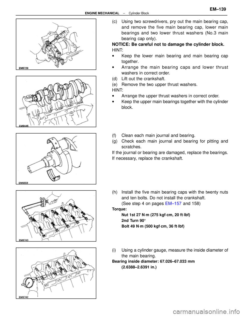
(c) Using two screwdrivers, pry out the main bearing cap,and remove the five main bearing cap, lower main
bearings and two lower thrust washers (No.3 main
bearing cap only).
NOTICE: Be careful not to damage the cylinder block.
HINT:
w Keep the lower main bearing and main bearing cap
together.
w Arrange the main bearing caps and lower thrust
washers in correct order.
(d) Lift out the crankshaft.
(e) Remove the two upper thrust washers.
HINT:
w Arrange the upper thrust washers in correct order.
w Keep the upper main bearings together with the cylinder
block.
(f) Clean each main journal and bearing.
(g) Check each main journal and bearing for pitting and scratches.
If the journal or bearing are damaged, replace the bearings.
If necessary, replace the crankshaft.
(h) Install the five main bearing caps with the twenty nuts and ten bolts. Do not install the crankshaft.
(See step 4 on pages EM±157 and 158)
Torque:
Nut 1st 27 N Vm (275 kgf Vcm, 20 ft Vlbf)
2nd Turn 90 5
Bolt 49 N Vm (500 kgf Vcm, 36 ft Vlbf)
(i) Using a cylinder gauge, measure the inside diameter of
the main bearing.
Bearing inside diameter: 67.026±67.033 mm
(2.6388±2.6391 in.)
±
ENGINE MECHANICAL Cylinder BlockEM±139
WhereEverybodyKnowsYourName