Page 1357 of 4087
INSPECTION OF EGR SYSTEM (USA
Spec.)
INSPECT SYSTEM OPERATION
(a) Using SST, connect terminals TE1 and E1 of the check(ºDIAGNOSISº) connector.
SST 09843±18020
(b) Keep the engine at 3,500 rpm.
(c) Set the transmission shift lever to the ºNº position.
(d) Remove the SST from the check connector.
SST 09843±18020
(e) Check whether the engine rpm increases 100±300 rpm under the following conditions.
Coolant temp.
Below 53 5C (127 5F) No increase
Above 55 5C (131 5F) Increases
±
EMISSION CONTROL SYSTEMS Exhaust Gas Recirculation (EGR) SystemEC±17
WhereEverybodyKnowsYourName
Page 1358 of 4087
INSPECTION OF EGR SYSTEM
(Exc. USA Spec.)
1. CHECK AND CLEAN FILTERS IN EGR VACUUMMODULATOR
(a) Remove the cap and filter.
(b) Check the filter for contamination or damage.
(c) Using compressed air, clean the filters.
(d) Reinstall the filter and cap.
HINT: Install the filter with the coarser surface facing the at-
mospheric side (outward).
2. INSPECT SYSTEM OPERATION (a) Using SST, connect terminals TE1 and E1 of the check
(ºDIAGNOSISº) connector.
SST 09843±18020
(b) Keep the engine at 3,500 rpm.
(c) Set the transmission shift lever to the ºNº position.
(d) Remove the SST from the check connector.
SST 09843±18020
(e) Check whether the engine rpm increases 100±300 rpm under the following conditions:
Coolant temp.
Below 53 5C (127 5F) No increase
Above 55 5C (131 5F) Increases
EC±18
±
EMISSION CONTROL SYSTEMS Exhaust Gas Recirculation (EGR) System
WhereEverybodyKnowsYourName
Page 1360 of 4087

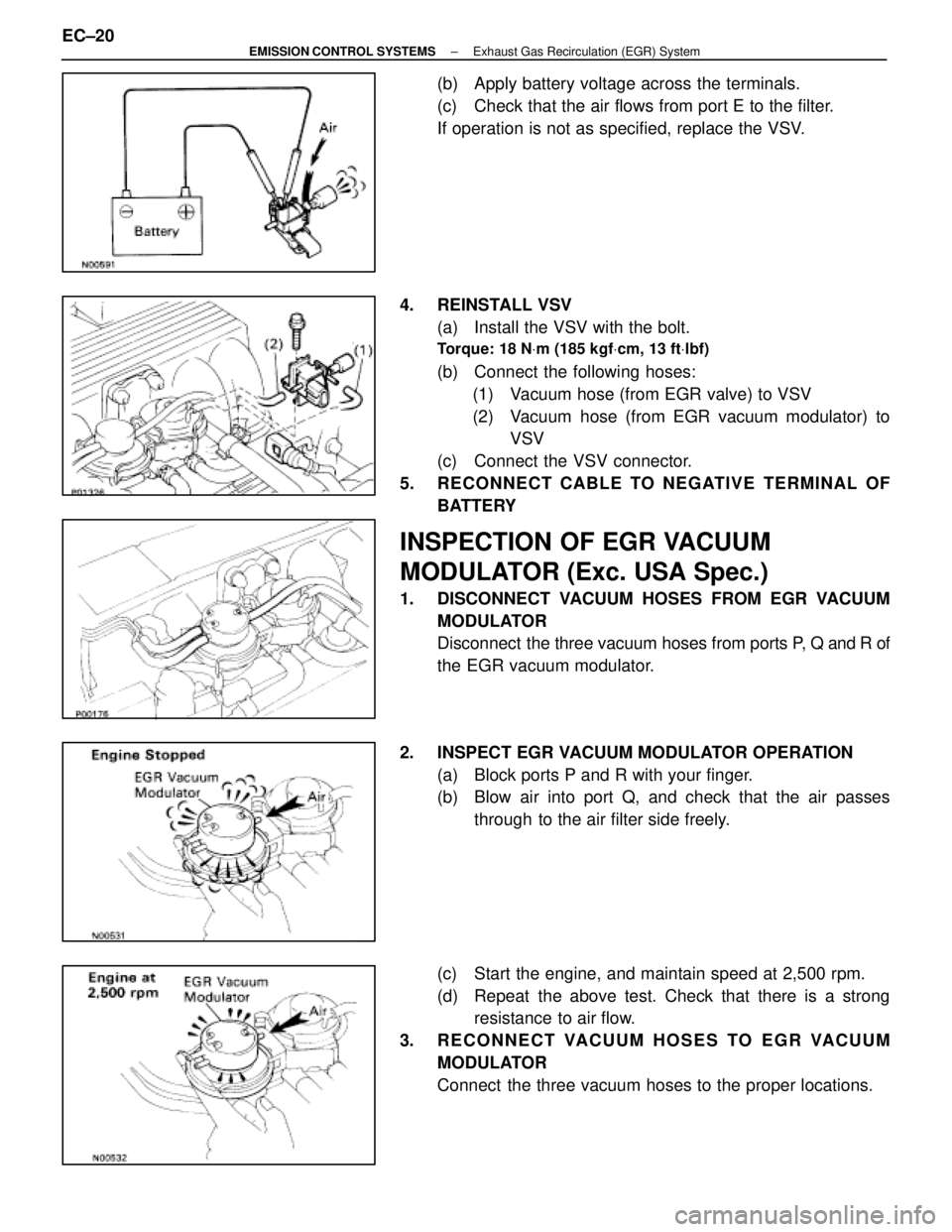
(b) Apply battery voltage across the terminals.
(c) Check that the air flows from port E to the filter.
If operation is not as specified, replace the VSV.
4. REINSTALL VSV (a) Install the VSV with the bolt.
Torque: 18 N Vm (185 kgf Vcm, 13 ft Vlbf)
(b) Connect the following hoses:
(1) Vacuum hose (from EGR valve) to VSV
(2) Vacuum hose (from EGR vacuum modulator) to VSV
(c) Connect the VSV connector.
5. RECONNECT CABLE TO NEGATIVE TERMINAL OF BATTERY
INSPECTION OF EGR VACUUM
MODULATOR (Exc. USA Spec.)
1. DISCONNECT VACUUM HOSES FROM EGR VACUUMMODULATOR
Disconnect the three vacuum hoses from ports P, Q and R of
the EGR vacuum modulator.
2. INSPECT EGR VACUUM MODULATOR OPERATION (a) Block ports P and R with your finger.
(b) Blow air into port Q, and check that the air passesthrough to the air filter side freely.
(c) Start the engine, and maintain speed at 2,500 rpm.
(d) Repeat the above test. Check that there is a strong resistance to air flow.
3. RECONNECT VACUUM HOSES TO EGR VACUUM MODULATOR
Connect the three vacuum hoses to the proper locations.
EC±20
±
EMISSION CONTROL SYSTEMS Exhaust Gas Recirculation (EGR) System
WhereEverybodyKnowsYourName
Page 1362 of 4087

INSPECTION OF EGR VALVE
(USA Spec.)
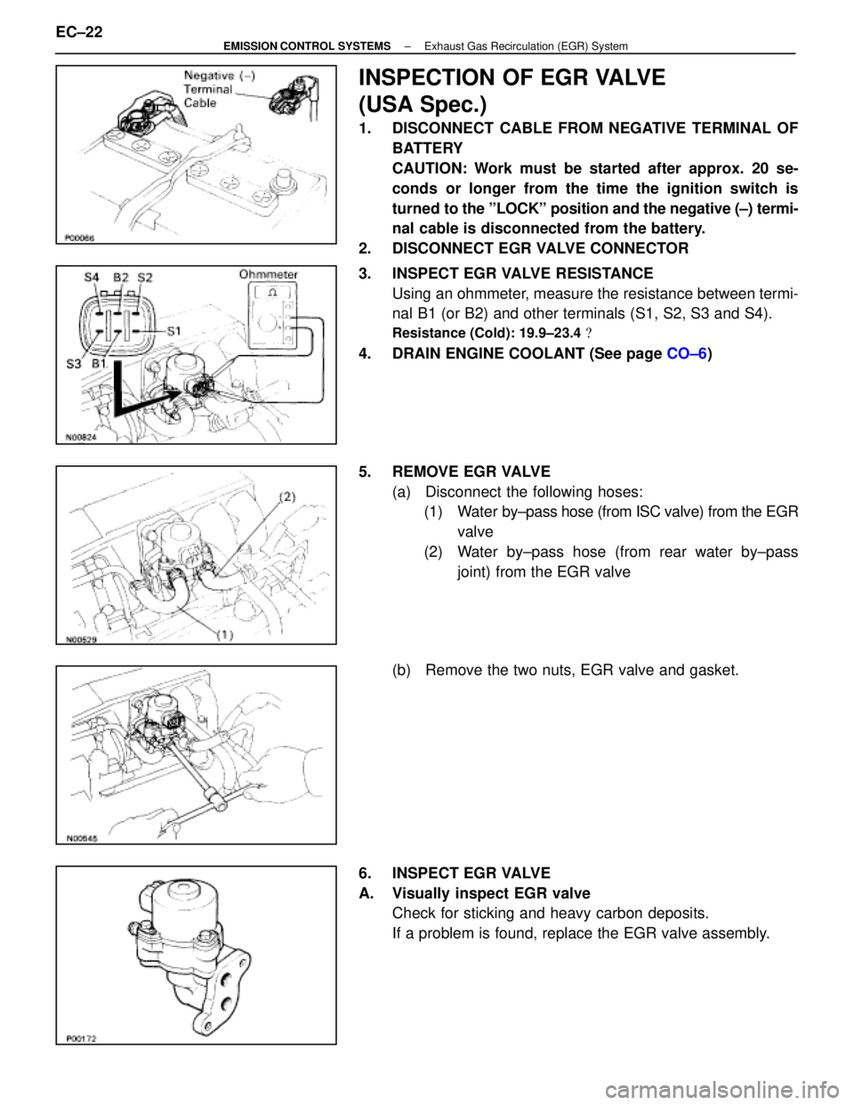
1. DISCONNECT CABLE FROM NEGATIVE TERMINAL OFBATTERY
CAUTION: Work must be started after approx. 20 se-
conds or longer from the time the ignition switch is
turned to the ºLOCKº position and the negative (±) termi-
nal cable is disconnected from the battery.
2. DISCONNECT EGR VALVE CONNECTOR
3. INSPECT EGR VALVE RESISTANCE Using an ohmmeter, measure the resistance between termi-
nal B1 (or B2) and other terminals (S1, S2, S3 and S4).
Resistance (Cold): 19.9±23.4 �
4. DRAIN ENGINE COOLANT (See page CO±6)
5. REMOVE EGR VALVE (a) Disconnect the following hoses:(1) Water by±pass hose (from ISC valve) from the EGR
valve
(2) Water by±pass hose (from rear water by±pass joint) from the EGR valve
(b) Remove the two nuts, EGR valve and gasket.
6. INSPECT EGR VALVE
A. Visually inspect EGR valve Check for sticking and heavy carbon deposits.
If a problem is found, replace the EGR valve assembly.
EC±22
±
EMISSION CONTROL SYSTEMS Exhaust Gas Recirculation (EGR) System
WhereEverybodyKnowsYourName
Page 1365 of 4087
3. INSPECT EGR VALVECheck for sticking and heavy carbon deposits.
If a problem is found, replace the EGR valve assembly.
4. REINSTALL EGR VALVE (a) Place a new gasket on the EGR valve adaptor.
NOTICE:
w Do not touch the adaptor and EGR valve surfaces of the
gasket with your hand.
w Align the port holes of the gasket and adaptor.
Be careful of the installation direction.
(b) Install the EGR valve with the two nuts.
Torque: 18 N Vm (185 kgf Vcm, 13 ft Vlbf)
(c) Install the vacuum modulator bracket to the EGR valve.
(d) Connect the following hoses:
(1) Vacuum hose (from VSV) to EGR valve
(2) Vacuum hose (from VSV) to EGR vacuum modula- tor
(3) Vacuum hose (from EGR vacuum modulator) to EGR valve
(4) Water by±pass hose (from ISC valve) to the EGR
valve
(5) Water by±pass hose (from rear water by±pass joint) to the EGR valve
5. REFILL WITH ENGINE COOLANT (See page CO±7)
±
EMISSION CONTROL SYSTEMS Exhaust Gas Recirculation (EGR) SystemEC±25
WhereEverybodyKnowsYourName
Page 1385 of 4087

TUNE±UP
EG10Z±05
ENGINE COOLANT INSPECTION
1. CHECK ENGINE COOLANT LEVEL AT RESERVOIR TANK
The coolant level should be above the ªCOLD LEVELº at nor-
mal temperature (20 5C (68 5F)).
If low, check for leaks and add coolant up to the ªCOLD LEV-
ELº
2. CHECK ENGINE COOLANT QUALITY
(a) Remove the radiator cap from the reservoir tank.
CAUTION: To avoid the danger of being burned, do not remove
it while the engine and radiator are still hot as fluid and steam
can be blown out under pressure
(b) There should not be any excessive deposits of rust or scale around the radiator cap or reservoir tank filler hole, and the
coolant should be free from oil.
If excessively dirty, clean the coolant passages and replace
the coolant.
Capacity (w/ Heater):
10.8 liters (11.4 US qts, 9.5 lmp. qts)
HINT:
wUse a good brand of ethylene±glycol base coolant and
mix it according to the manufacturer's directions.
w Using coolant which includes more than 50%
ethylene±glycol(but not more than 70%) is
recommended.
NOTICE:
w Do not use a alcohol type coolant.
w The coolant should be mixed with demineralized water or
distilled water.
(c) Reinstall the radiator cap.
±
1UZ±FE ENGINE ENGINE MECHANICALEG±9
WhereEverybodyKnowsYourName
Page 1386 of 4087

EG0B4±0K
ENGINE OIL INSPECTION
1. CHECK OIL QUALITYCheck the oil for deterioration, entry of water, discoloring or
thinning.
If oil quality is visibly poor, replace the oil.
Oil grade:
API grade SG or SH, Energy±Conserving II or ILSAC
multigrade engine oil. Recommended viscosity is as
shown in the illustration, with SAE 5W±30 being the
preferred engine oil.
Drain and refill capacity: w/ Oil filter change
4.8 liters (5.1 US qts, 4.2 lmp. qts)
w/o Oil filter change
4.5 liters (4.8 US qts, 4.0 lmp. qts)
2. CHECK ENGINE OIL LEVELThe oil level should be between the ªLº and ªFº marks on the
dipstick.
If low, check for leakage and add oil up to the ªFº mark.
EG3E2±01
BATTERY INSPECTION
1. CHECK BATTERY ELECTROYTE LEVEL AND VOLTAGE
(a) Check the electrolyte quantity of each cell.If under the lower level, replace the battery (or add distilled
water if possible.). Need to check the charging system.
(b) Measure the battery voltage between the terminals negative (±) and positive (+) of the battery.
Standard voltage:
12.7±12.9 V at 20 5C (68 5F)
HINT:
w Before measuring the voltage, turn the ignition switch
OFF and turn off the electrical systems (headlight,
blower motor, rear defogger etc.) for 60 seconds to
remove the surface charge.
EG±10
±
1UZ±FE ENGINE ENGINE MECHANICAL
WhereEverybodyKnowsYourName
Page 1387 of 4087
wIf the vehicle has been running, wait 5 minutes or more
after the vehicle stops before measuring the battery
voltage.
If the voltage is less than specification, charge the battery.
HINT: Check the indicator as shown in the illustration.
1. C H E C K B AT T E RY S P E C I F I C G R AV I T Y A N D ELECTROLYTE LEVEL
2. CHECK BATTERY TERMINALS AND FUSES
(a) Check that the battery terminals are not loose or corroded.
(b) Check the fuses for continuity.
EG3F9±01
AIR FILTER INSPECTION AND
CLEANING
1. REMOVE AIR FILTER
(a) Open the air cleaner cap.
(b) Remove the air filter.
±
1UZ±FE ENGINE ENGINE MECHANICALEG±11
WhereEverybodyKnowsYourName