Page 1049 of 4087

SPEED SENSOR SIGNAL CHECK
1. Turn the ignition switch to OFF.
2. Using SST, connect terminals Ts and E1 of DLC1.SST 09843±18020
3. Start the engine.
4. Check that the ABS warning light blinks. HINT: If the ABS warning light does not blink, inspect the ABS
warning light circuit (see page BR±144).
5. Drive vehicle straight forward. HINT: Drive vehicle faster than 45 km/h (28 mph) for several
seconds.
6. Stop the vehicle.
7. Using SST, connect terminals Tc and E1 of DLC1.
SST 09843±18020
8. Read the number of blinks of the ABS warning light. HINT: See the list of diagnosis trouble codes shown on the
next page.
If every sensor is normal, a normal code is output (A cycle of
0.25 sec. on and 0.25 sec. OFF is repeated).
If 2 or more malfunction are indicated at the same time, the
lowest numbered code will be displayed 1st.
9. After performing the check, disconnect terminals Ts and E1,Tc and E1 of DLC1, and ignition switch turned off.
BR±80
±
BRAKE SYSTEM ANTI±LOCK BRAKE SYSTEM (ABS)
WhereEverybodyKnowsYourName
Page 1098 of 4087

OKNG
NGOK
OKNG
3Check harness and connector between ABS & TRAC ECU and TRAC pump & motor (Se\
e page
IN±33).
Repair or replace harness or connector.
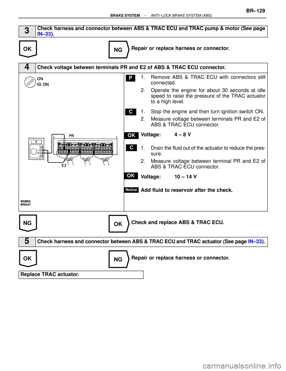
4Check voltage between terminals PR and E2 of ABS & TRAC ECU connector.
C
OK
P
OK
C
Notice
1. Remove ABS & TRAC ECU with connectors still
connected.
2. Operate the engine for about 30 seconds at idle speed to raise the pressure of the TRAC actuator
to a high level.
1. Stop the engine and then turn ignition switch ON.
2. Measure voltage between terminals PR and E2 of ABS & TRAC ECU connector.
Voltage: 4 ± 8 V
1. Drain the fluid out of the actuator to reduce the pres-
sure.
2. Measure voltage between terminal PR and E2 of ABS & TRAC ECU connector.
Voltage: 10 ± 14 V
Add fluid to reservoir after the check.
Check and replace ABS & TRAC ECU.
5Check harness and connector between ABS & TRAC ECU and TRAC actuator (See page IN±33).
Repair or replace harness or connector.
Replace TRAC actuator.
±
BRAKE SYSTEM ANTI±LOCK BRAKE SYSTEM (ABS)BR±129
WhereEverybodyKnowsYourName
Page 1100 of 4087
NGOK
OKNG
INSPECTION PROCEDURES
1Check voltage between terminals PR and E21 of ABS & TRAC ECU connector.
C
OK
P1. Remove ABS & TRAC ECU with connectors stillconnected.
2. Operate the engine for about 30 seconds at idle speed to raise the pressure of the TRAC actuator
to a high level.
1. Stop the engine and then turn ignition switch ON.
2. Measure voltage between terminals PR and E2 of ABS & TRAC ECU connector.
Voltage: 4 ± 8 V for more than 24 sec.
Check and replace ABS & TRAC ECU.
2Check for brake fluid leakage.
See page BR±150.
Repair brake fluid leakage and add fluid.
Replace TRAC accumulator.
If TRAC accumulator is replaced and the problem is still occurring, repl\
ace TRAC actuator.
±
BRAKE SYSTEM ANTI±LOCK BRAKE SYSTEM (ABS)BR±131
WhereEverybodyKnowsYourName
Page 1105 of 4087
NGOK
OKNG
INSPECTION PROCEDURE
1Check voltage between terminals PR and E2 of ABS & TRAC ECU connector.
C
OK
P
C
Notice
1. Remove ABS & TRAC ECU with connectors stillconnected.
2. Operate the engine for about 30 seconds at idle speed to raise the pressure of TRAC actuator to a
high level.
1. Stop the engine and then turn ignition switch ON.
2. Measure voltage between terminals PR and E2 of ABS & TRAC ECU connector.
Voltage: 4 ± 8 V
1. Drain the fluid out of the actuator to reduce the pres-
sure (See page BR±48).
2. Measure voltage between terminals PR and E2 of ABS & TRAC ECU connector.
Voltage: 10 ± 14 V
Add fluid to reservoir after the check.
Check and replace ABS & TRAC ECU.
2Check harness and connector between ABS & TRAC ECU and TRAC actuator (See page IN±33).
Repair or replace harness or connector.
Replace TRAC actuator.
BR±136±
BRAKE SYSTEM ANTI±LOCK BRAKE SYSTEM (ABS)
WhereEverybodyKnowsYourName
Page 1119 of 4087
IN±33 ).
WIRING DIAGRAM
Ts Terminal Circuit
CIRCUIT DESCRIPTION
The sensor check circuit detects abnormalities in the speed sensor signal w\
hich can not be detected with
the diagnostic trouble code check.Connecting terminals Ts and E1 of the DLC1 in the engine compartment
starts the check.
DIAGNOSTIC CHARTDIAGNOSTIC CHART
BR±150±
BRAKE SYSTEM ANTI±LOCK BRAKE SYSTEM (ABS)
WhereEverybodyKnowsYourName
Page 1133 of 4087
DESCRIPTION
The alternator is a small, high±rpm, high±performance type with an IC\
regulator incorporated. The IC regula-
tor uses integrated circuits and controls the voltage produced by the alter\
nator.
PRECAUTIONS
1. Check that the battery cables are connected to the correct terminals.
2. Disconnect the battery cables when the battery is given a quick charge.
3. Do not perform tests with a high voltage insulation resistance tester.
4. Never disconnect the battery when the engine is running. CH±2
±
CHARGING SYSTEM Description, Precautions
WhereEverybodyKnowsYourName
Page 1134 of 4087
DESCRIPTION
The alternator is a small, high±rpm, high±performance type with an\
IC regulator incorporated. The IC regula-
tor uses integrated circuits and controls the voltage produced by the alter\
nator.
PRECAUTIONS
1. Check that the battery cables are connected to the correct terminals.
2. Disconnect the battery cables when the battery is given a quick charge.
3. Do not perform tests with a high voltage insulation resistance tester.
4. Never disconnect the battery when the engine is running. CH±2
±
CHARGING SYSTEM Description, Precautions
WhereEverybodyKnowsYourName
Page 1137 of 4087

ON±VEHICLE INSPECTION
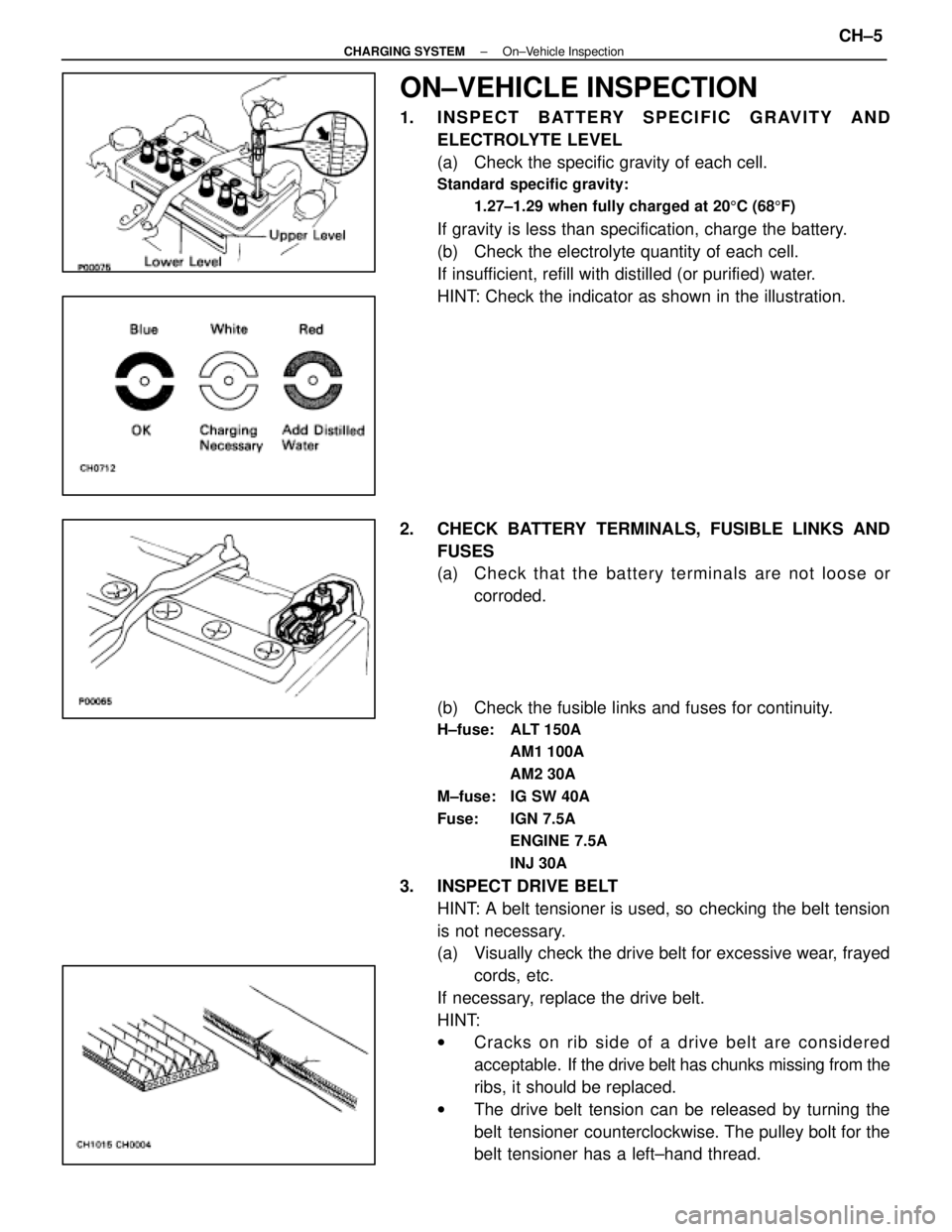
1. INSPECT BATTERY SPECIFIC GRAVITY ANDELECTROLYTE LEVEL
(a) Check the specific gravity of each cell.
Standard specific gravity:
1.27±1.29 when fully charged at 20 5C (68 5F)
If gravity is less than specification, charge the battery.
(b) Check the electrolyte quantity of each cell.
If insufficient, refill with distilled (or purified) water.
HINT: Check the indicator as shown in the illustration.
2. CHECK BATTERY TERMINALS, FUSIBLE LINKS AND FUSES
(a) Check that the battery terminals are not loose orcorroded.
(b) Check the fusible links and fuses for continuity.
H±fuse: ALT 150A AM1 100A
AM2 30A
M±fuse: IG SW 40A
Fuse: IGN 7.5A ENGINE 7.5A
INJ 30A
3. INSPECT DRIVE BELTHINT: A belt tensioner is used, so checking the belt tension
is not necessary.
(a) Visually check the drive belt for excessive wear, frayedcords, etc.
If necessary, replace the drive belt.
HINT:
w Cracks on rib side of a drive belt are considered
acceptable. If the drive belt has chunks missing from the
ribs, it should be replaced.
w The drive belt tension can be released by turning the
belt tensioner counterclockwise. The pulley bolt for the
belt tensioner has a left±hand thread.
±
CHARGING SYSTEM On±Vehicle InspectionCH±5
WhereEverybodyKnowsYourName