Page 295 of 4087

MEASURE LINE PRESSURE
NOTICE:
�Perform the test at normal operating fluid temperature 50±80 �C (122±176 �F).
� The line pressure test should always be carried out in pairs. One technicia\
n should observe the
conditions of wheels or wheel stoppers outside the vehicle while the other is perf\
orming the test.
� Be careful to prevent the oil pressure gauge hose from interfering with \
the exhaust pipe.
(a) Warm up the transmission fluid.
(b) Remove the test plug on the transmission case left side and connect the \
oil pressure gauge SST.
SST 09992±00094
HINT: Connecting the oil pressure gauge will be made easier by moving LH sid\
e heat insulator aside.
(c) Fully apply the parking brake and chock the 4 wheels.
(d) Start the engine and check idling RPM.
(e) Keep your left foot pressed firmly on the brake pedal and shift into D p\
osition.
(f) Measure the line pressure when the engine is idling.
(g) Press the accelerator pedal all the way down. Quickly read the highest line pressure when engine speedreaches stall speed.
(h) In the same manner, perform the test in R position. AT±54
±
A304E (1UZ±FE) AUTOMATIC TRANSMISSION TROUBLESHOOTING
WhereEverybodyKnowsYourName
Page 298 of 4087
(f) Fully apply the parking brake and chock the 4 wheels.
(g) Start the engine and check idling RPM.
(h) Keep your left foot pressed firmly on the brake pedal and shift into D p\
osition.
(i) Measure the accumulator back pressure.
(j) With the conditions the same as in (h), ground the other probe of the test\
lead which has one end insertedinto the terminal SLN of the ECM harness side connector, then measure the accumulator back pressure
again.
±
A304E (1UZ±FE) AUTOMATIC TRANSMISSION TROUBLESHOOTINGAT±57
WhereEverybodyKnowsYourName
Page 343 of 4087
OKNG
OKNG
OKNG
INSPECTION PROCEDURE
1Main throttle position signal check.
C
OK
Hint
PTurn ignition switch ON (Do not start the engine).
Check voltage at the terminal T
T of the DLC2 while grad-
ually depressing the accelerator pedal from the fully
closed position to the fully opened position.
Voltage changes from 0 V to 8 V by stages.
Do not depress the brake pedal during this test. The
voltage will stay at 0 V if depressed.
Proceed to next circuit inspection shown on matrix chart
(See page AT±66).
2Check throttle position sensor.
See engine troubleshooting section in EG section.
Replace throttle position sensor.
3Check harness and connector between ECM and throttle position sensor (S\
ee page IN±33).
Repair or replace harness or connector.
Check and replace ECM.
±
A304E (1UZ±FE) AUTOMATIC TRANSMISSION TROUBLESHOOTINGAT±103
WhereEverybodyKnowsYourName
Page 345 of 4087
OKNG
OKNG
OKNG
INSPECTION PROCEDURE
1Check voltage between terminal KD of ECM connector and body ground.
C
OK
P1. Connect the check harness A to the ECM (See EGsection).
2. Turn ignition switch ON (Do not start the engine.)
Measure voltage between terminal KD of ECM connec-
tor and body ground when accel. pedal is fully de-
pressed or not.
Proceed to next circuit inspection shown on matrix chart
(See page AT±66).
2Check kick±down switch.
C
OK
1. Disconnect dick±down switch connector. (See page AT±18)
2. Measure resistance between terminals 1 and 2 of kick±down switch connector when kick±down
switch is ON and OFF
Replace kick±down switch.
3Check harness and connector between ECM and kick±down switch, kick±down\
switch and
body ground (See page IN±33).
Repair or replace harness or connector.
Check and replace ECM
±
A304E (1UZ±FE) AUTOMATIC TRANSMISSION TROUBLESHOOTINGAT±105
WhereEverybodyKnowsYourName
Page 349 of 4087
OKNG
OKNG
OKNG
INSPECTION PROCEDURE
1Check operation of stop light.
Check if the stop lights go on and off normally when the brake pedal is operated and released.C
Check and repair stop light circuit (See BE section).
2Check stop light signal.
C
OK
1. Connect voltmeter to the terminals TT and E1 of the
DLC2.
2. Turn ignition switch ON (Do not start the engine).
3. Fully depress the accelerator pedal until the volt- meter indicates 8 V and hold it.
4. Depress and release the brake pedal and check the
voltage.
Proceed to next circuit inspection shown on matrix chart
(See page AT±66).
3Check harness and connector between ECM and stop light switch (See page\
IN±33).
Repair or replace harness or connector.
Check and replace ECM.
±
A304E (1UZ±FE) AUTOMATIC TRANSMISSION TROUBLESHOOTINGAT±109
WhereEverybodyKnowsYourName
Page 389 of 4087
INSTALLATION MAIN POINTS
AT00L±01
1. CHECK TORQUE CONVERTER CLUTCH INSTALLATIONUsing calipers and a straight edge, measure from the
installed surface of the torque converter clutch to the front
surface of the transmission housing.
Correct distance:
17.1 mm (0.673 in.)
If the distance is less than the standard, check for an improp-
er installation.
2. LIFT ENGINE FRONT SIDE
3. INSTALL THROTTLE CABLE
4. ADJUST THROTTLE CABLE (See page AT±48)
5. FILL TRANSMISSION WITH ATF AND CHECK FLUID LEVEL
(See page AT±47)
NOTICE: Do not overfill.
Fluid type:
ATF Type T±II or equivalent
6. INSTALL PROPELLER SHAFT(See page PR±12 to PR±14 )
7. INSTALL EXHAUST PIPE
(See page EG±204)
AT±26
±
A304E (1UZ±FE) AUTOMATIC TRANSMISSION ASSEMBLY REMOVAL AND INSTALLATION
WhereEverybodyKnowsYourName
Page 437 of 4087

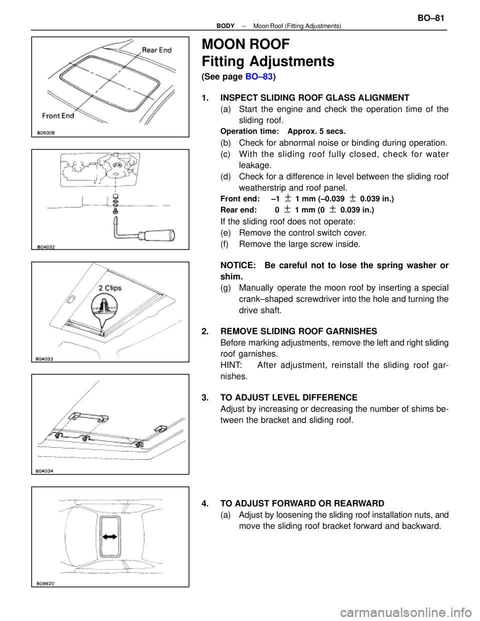
MOON ROOF
Fitting Adjustments
(See page BO±83)
1. INSPECT SLIDING ROOF GLASS ALIGNMENT (a) Start the engine and check the operation time of thesliding roof.
Operation time: Approx. 5 secs.
(b) Check for abnormal noise or binding during operation.
(c) With th e slid in g ro o f fu lly clo se d , ch e ck fo r wa te rleakage.
(d) Check for a difference in level between the sliding roof weatherstrip and roof panel.
Front end: ±1 + 1 mm (±0.039 + 0.039 in.)
Rear end: 0
+ 1 mm (0 + 0.039 in.)
If the sliding roof does not operate:
(e) Remove the control switch cover.
(f) Remove the large screw inside.
NOTICE: Be careful not to lose the spring washer or
shim.
(g) Manually operate the moon roof by inserting a special crank±shaped screwdriver into the hole and turning the
drive shaft.
2. REMOVE SLIDING ROOF GARNISHES Before marking adjustments, remove the left and right sliding
roof garnishes.
HINT: After adjustment, reinstall the sliding roof gar-
nishes.
3. TO ADJUST LEVEL DIFFERENCE Adjust by increasing or decreasing the number of shims be-
tween the bracket and sliding roof.
4. TO ADJUST FORWARD OR REARWARD (a) Adjust by loosening the sliding roof installation nuts, andmove the sliding roof bracket forward and backward.
±
BODY Moon Roof (Fitting Adjustments)BO±81
WhereEverybodyKnowsYourName
Page 537 of 4087

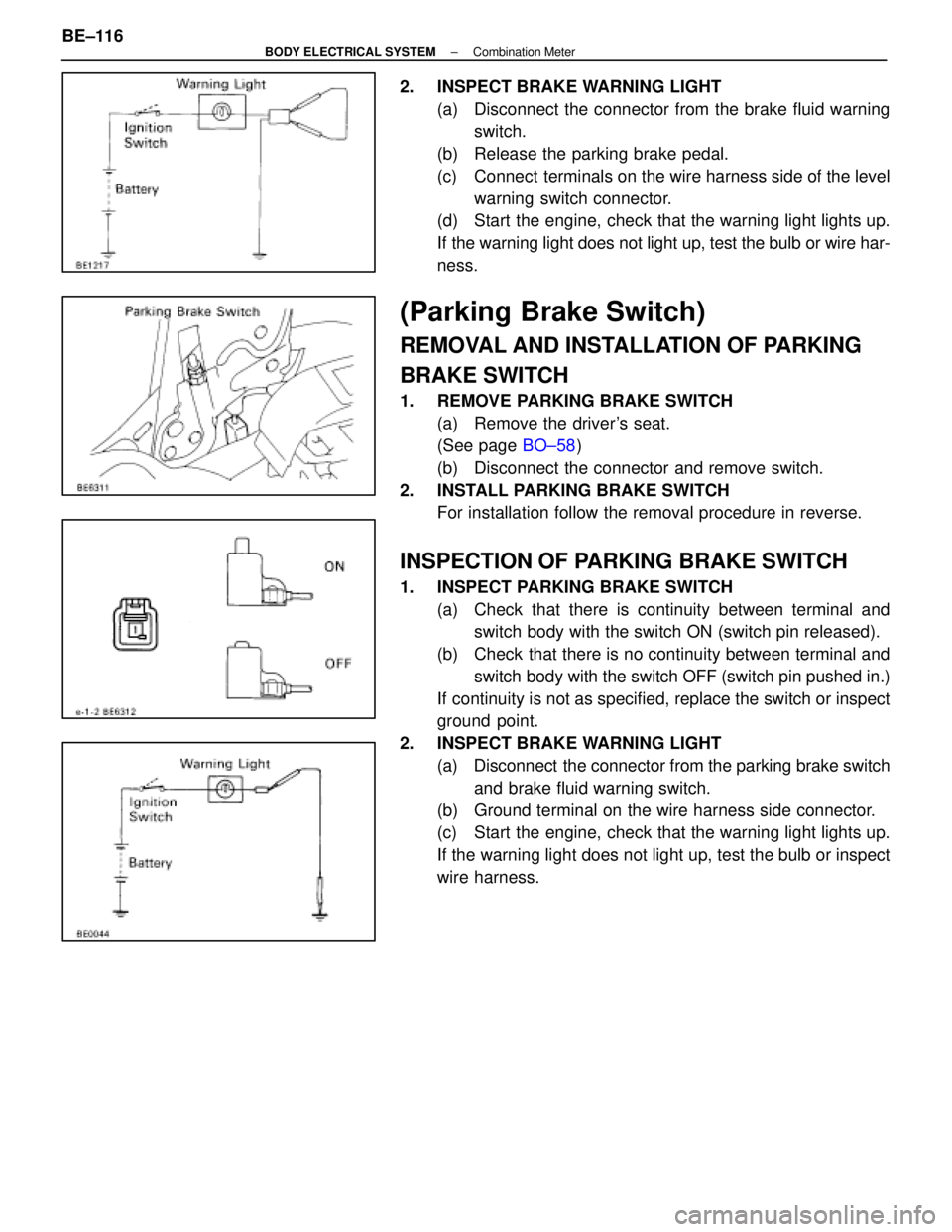
2. INSPECT BRAKE WARNING LIGHT(a) Disconnect the connector from the brake fluid warningswitch.
(b) Release the parking brake pedal.
(c) Connect terminals on the wire harness side of the level warning switch connector.
(d) Start the engine, check that the warning light lights up.
If the warning light does not light up, test the bulb or wire har-
ness.
(Parking Brake Switch)
REMOVAL AND INSTALLATION OF PARKING
BRAKE SWITCH
1. REMOVE PARKING BRAKE SWITCH
(a) Remove the driver's seat.
(See page BO±58)
(b) Disconnect the connector and remove switch.
2. INSTALL PARKING BRAKE SWITCH For installation follow the removal procedure in reverse.
INSPECTION OF PARKING BRAKE SWITCH
1. INSPECT PARKING BRAKE SWITCH
(a) Check that there is continuity between terminal andswitch body with the switch ON (switch pin released).
(b) Check that there is no continuity between terminal and switch body with the switch OFF (switch pin pushed in.)
If continuity is not as specified, replace the switch or inspect
ground point.
2. INSPECT BRAKE WARNING LIGHT (a) Disconnect the connector from the parking brake switchand brake fluid warning switch.
(b) Ground terminal on the wire harness side connector.
(c) Start the engine, check that the warning light lights up.
If the warning light does not light up, test the bulb or inspect
wire harness.
BE±116
±
BODY ELECTRICAL SYSTEM Combination Meter
WhereEverybodyKnowsYourName